
[ad_1]
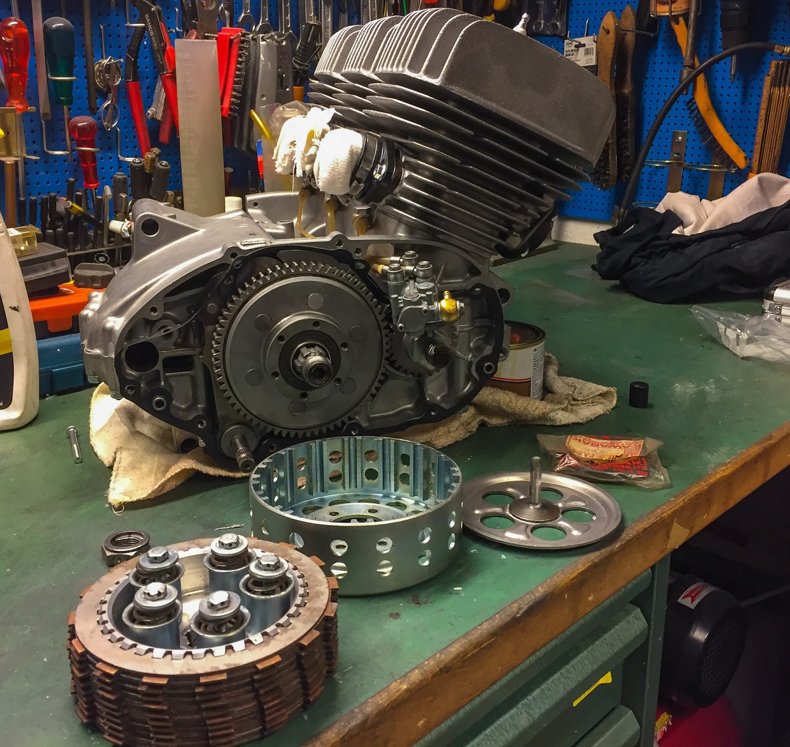
Since final time I’ve been busy at work and likewise making an attempt to find elements, getting elements fastened right here and there and likewise fettling a bit on my own within the storage. The following large transfer on the venture is getting the engine again in to the body. I need the engine to be kind of accomplished and completed once I do this lifting. I do know, it’s lighter to raise it in with out clutch and stator and so on, however additionally it is quite a bit simpler to work on the engine when it’s out of the body, on the bench. The motor has been sitting on the proper aspect of my working space since getting back from Malmö final winter.
After a few months I seen an oil leak from the clutch cowl… We suspected this to occur, Ebbe and I, since we by no means airplane floor the clutch cowl nor metallic sprayed the first drive sealing floor. It was apparent the oil got here from 2 areas. Partly from the underside of the clutch cowl and partly from the big oil seal within the aspect of the quilt. The engine had been again to Malmö and Ebbe had all of it floor and stuck. All I needed to do was mount the clutch cowl and clutch once more. Simple? Nicely, let´s see…..!

Good and simple does it… Nicely rested mechanic (me), all elements wanted current, the elements diagram on the iPad and right here we go! If you find yourself in no hurry, that is good work. You’ve time to determine issues out. How does it work? How did the Japanese engineers suppose? Good music on the radio and the hours are inclined to fly away shortly.
The one half that goes contained in the clutch cowl is the large major drive. This sits on two needle bearings and has an inside oil seal that may be seen near the shaft within the image to the left. The elements actually can sit just one approach and that makes it straightforward to resolve whenever you´re finished.
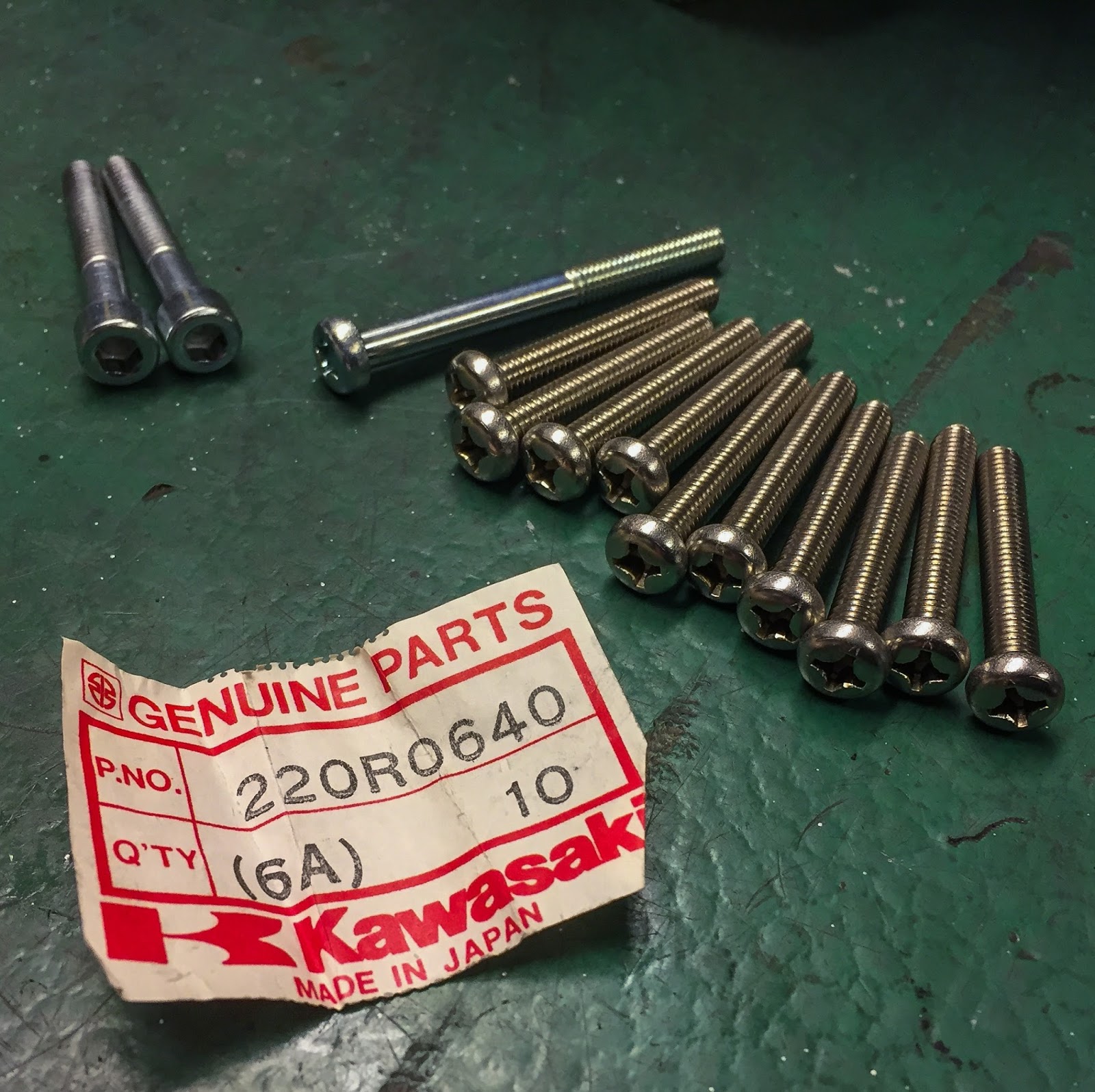
Subsequent was the clutch cowl. I had sourced new screws (NOS) for this job. I’m no fan of Allen bolts in any respect and particularly not on a seventies racer. 220R0640 is the half quantity for the shorter ones. 8 in all plus one longer.

Now that I obtained the screws mounted on the quilt I´m having doubts they’re right despite the fact that they got here in an unique elements bag with the proper half quantity… I consider Kawasaki have changed the unique hard-to-find pan head screws with a more moderen sort. I’ll have to repair that later!

The massive O-ring, sealing between the quilt and the first drive nonetheless felt contemporary and tender. Somewhat rubber grease on the lips of it and on the contemporary sealing floor of the first drive made it slide on fairly simply. You possibly can see the clutch push rod contained in the axle. Apparently there´s no “ball” within the H1R:s clutch mechanism. All the road bikes have them, however not right here. One other one of many small mysteries on these bikes that must be found out.
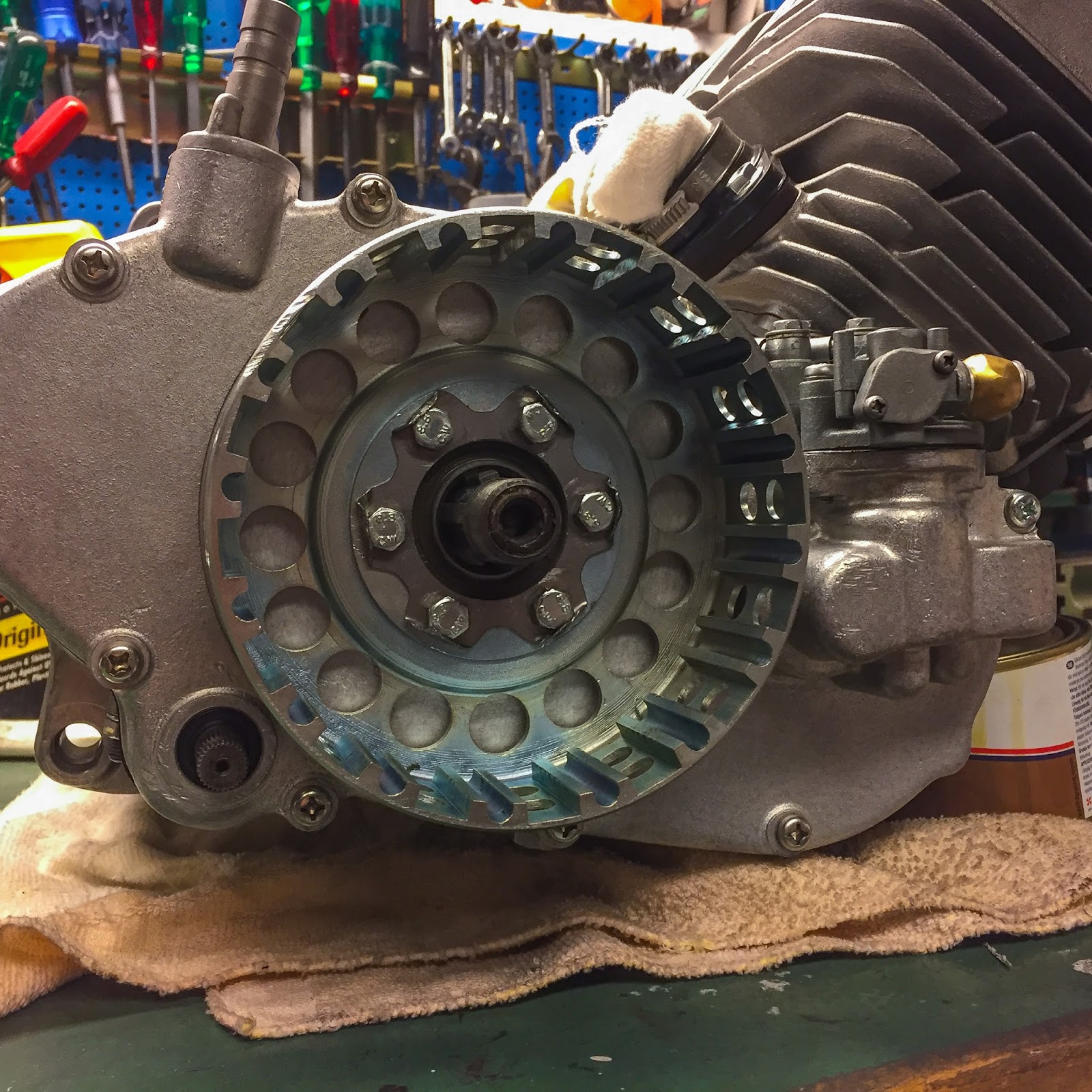
Subsequent was the outer clutch housing. Loctite AND the repro lock washer. Double safety right here.

Internal clutch hub was subsequent. That is secured to the shaft by a big 20mm nut initially secured by a lock washer solely. In the present day I used Loctite and held the interior hub with a particular device made for the H1 and H2 road bikes. It labored advantageous additionally right here, despite the fact that it couldn´t enter the hub the identical approach as on the road bikes.
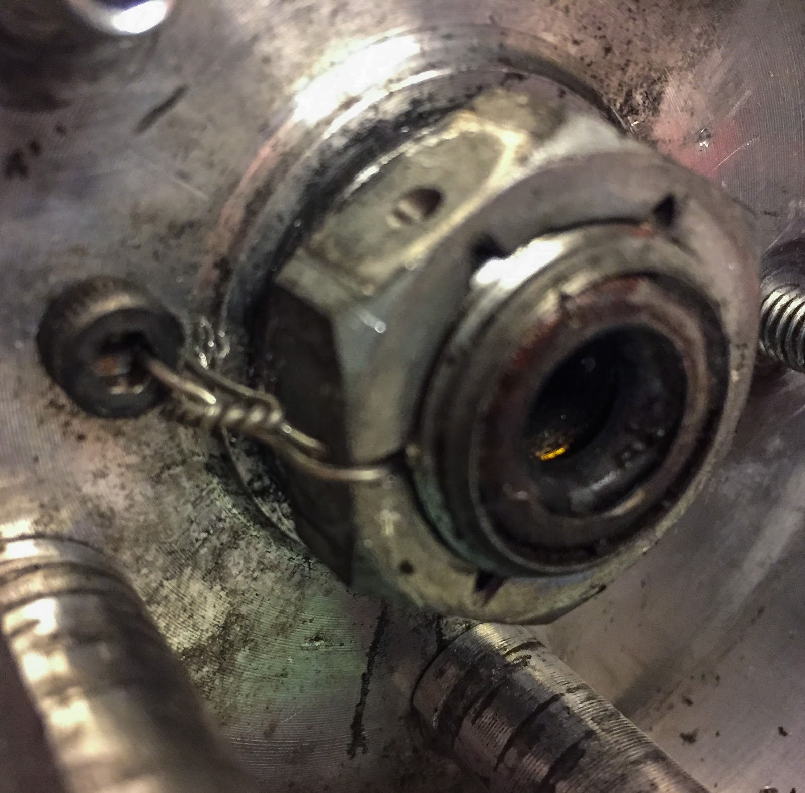
After “Esso” misplaced his clutch in a race in 1970 I feel he made this modification to the clutch hub securing. He drilled holes within the giant nut and put a ten.9 grade allen screw into the underside of the interior hub to have the ability to security wire the clutch hub to the shaft. Fairly good and ingenious, so I´m going that approach additionally!

Ending up the clutch aspect of the engine is only a matter of following the elements diagram. Begin out with one of many two outer metal plates on the backside and steel-fiber plates till you finish it with the final outer metal plate simply contained in the stress plate. All of the screws are secured with Loctite. I don´t suppose they have been secured by wire initially however they’re drilled for it so perhaps “Esso” really did use wire additionally right here. Stays to be seen…

For now I´m going to go away it like this. Ebbe promised me it is not going to come undone when Loctite is used. Anyway, I feel it appears to be like quite a bit higher with out the wire. The issue utilizing wire right here is that the stress plate will transfer outwards whenever you pull the clutch deal with and the wiring should be slack sufficient to permit that motion. I´ll give it some thought and perhaps I´ll give you one thing that appears OK and works the best way it ought to.

Subsequent up have been the deal with bar elements. Brake-, and clutch levers, throttle assy and the choke lever. I wanted to repair a screw that clamps the brake lever to the deal with bar. I had a pleasant one, re chromed years in the past simply needing a thread clear.
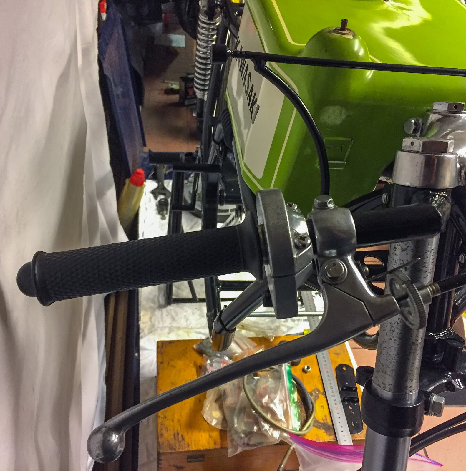
The suitable aspect kind of completed. The throttle grip and brake lever have been already finished, simply ready to be mounted on the bike. I feel this place is right with the rounded finish a part of the deal with bar protruding by means of the open finish of the throttle grip. I used to be additionally in a position to get the brake cable into the lever after I put the 2 cables in place down on the wheel. I consider that is the proper sequence.

The left brake plate kind of accomplished! The cable must be secure tied with a cotter pin and all of the bolts and nuts security wired. I´ll do all of that once I´m optimistic I’ve all of it on right.
The choke lever and the clutch lever in place on the left aspect. I´ll wait with the rubber grip till I´m optimistic I’ve every thing right right here ass nicely. The grip is absolutely refurbished and absolutely usable however I don´t need to take it off yet another time if I don´t need to…
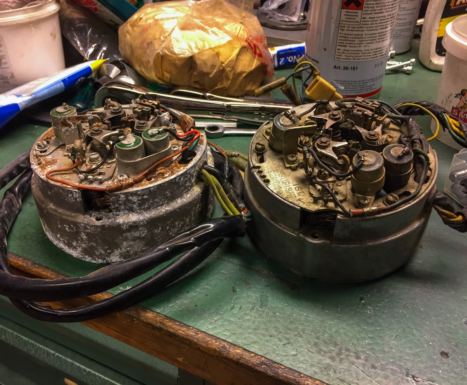
I’ve additionally began engaged on the stator and ignition on the bike. The unique yoke on the left and one from an H1B 1972 with factors ignition i Purchased on eBay on the proper. They DO look comparable! The condensers are totally different and likewise the size of the wiring. The H1B even have a bigger generator and extra windings to be able to provide electrical energy for the road tools resembling lights, horn flashers and so on. I´m going to try to rebuild as a lot as I can utilizing bits and items from the H1B to make the unique stator work pretty much as good as doable. Extra about this a part of the venture later. For now I´m glad to have a lot of the elements in my store. I´m nonetheless searching for the ignition cam 21103-004 and likewise the cam plate 21106-003. I have no idea why Kawasaki have totally different half numbers on the ignition cams right here. One motive will be they really ARE totally different in angles, length or what-not?? The timing cam plate is identical quantity, although… Fascinating!
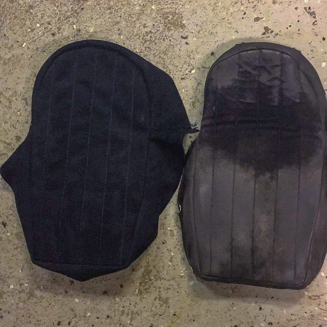
Bear in mind my adventures with reproducing the seat cowl? Nicely, my stitching abilities din´t fairly suffice right here so I visited NCCR in Delsbo and left the manufacturing to Pär Svedin who works at NCCR and likewise is a tailor. He´s been engaged on the covers and have them templated for manufacturing.
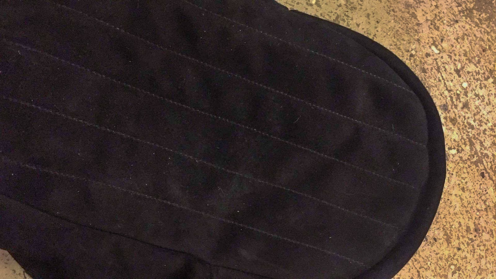
He despatched me some photos of the progress to this point. The fabric right here is actual suede leather-based he had in inventory. Appears to be like completely beautiful to me!
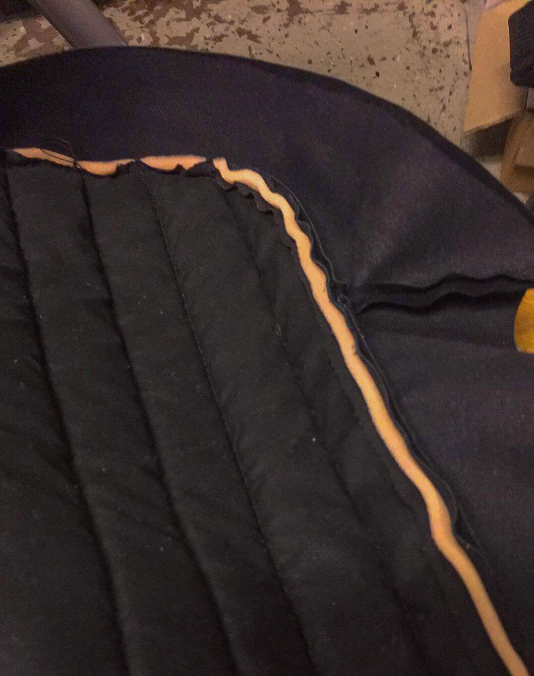
He´s utilizing a barely thinner liner/padding on the beneath aspect in comparison with what I used. Clearly an enchancment.

These covers will probably be near good in my ebook! I hope I´ll be capable to present you the completed product inside a coupe of weeks. I´m going to have a minimum of 3 covers made this time. One is perhaps in brown, we´ll see…
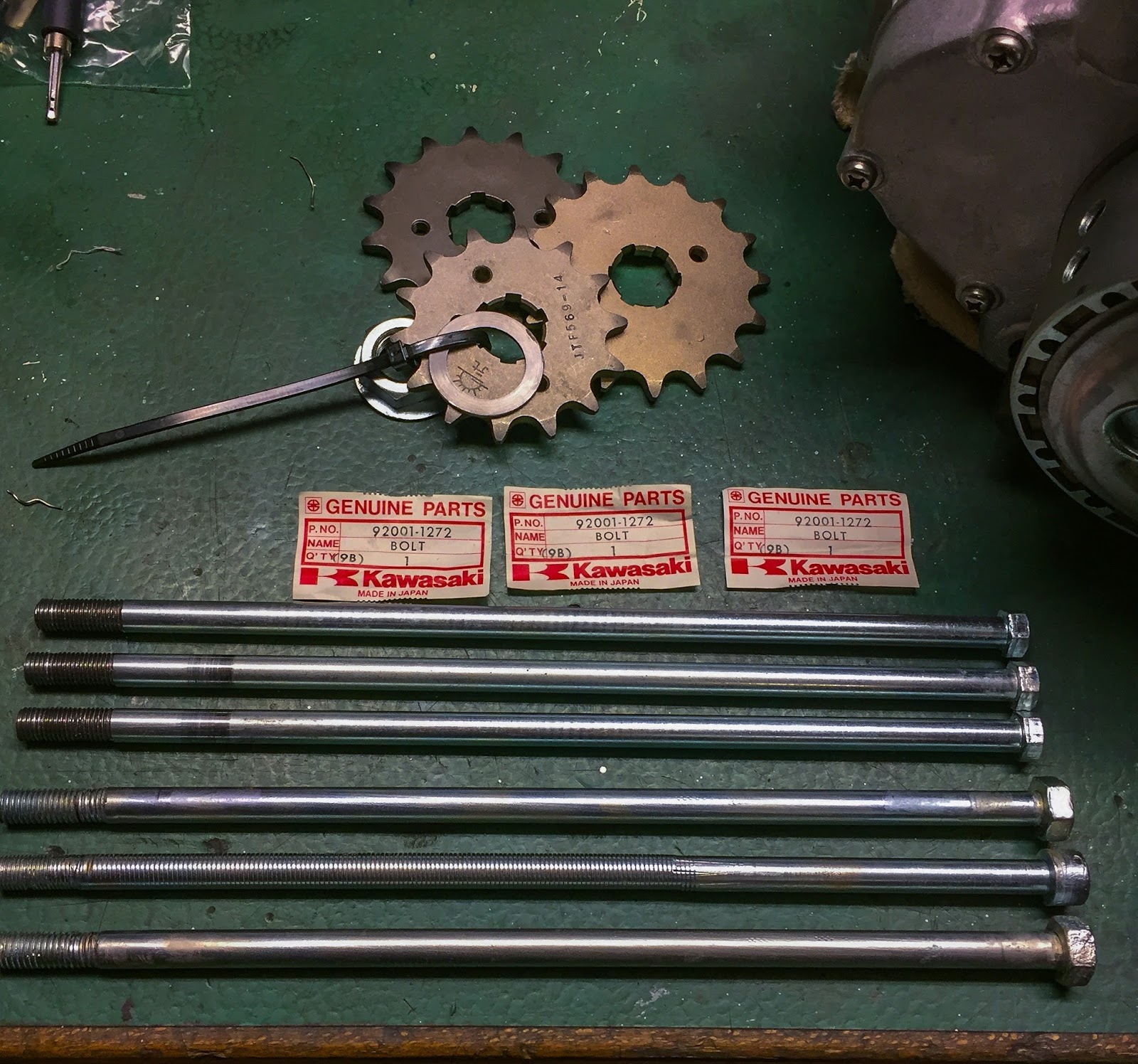
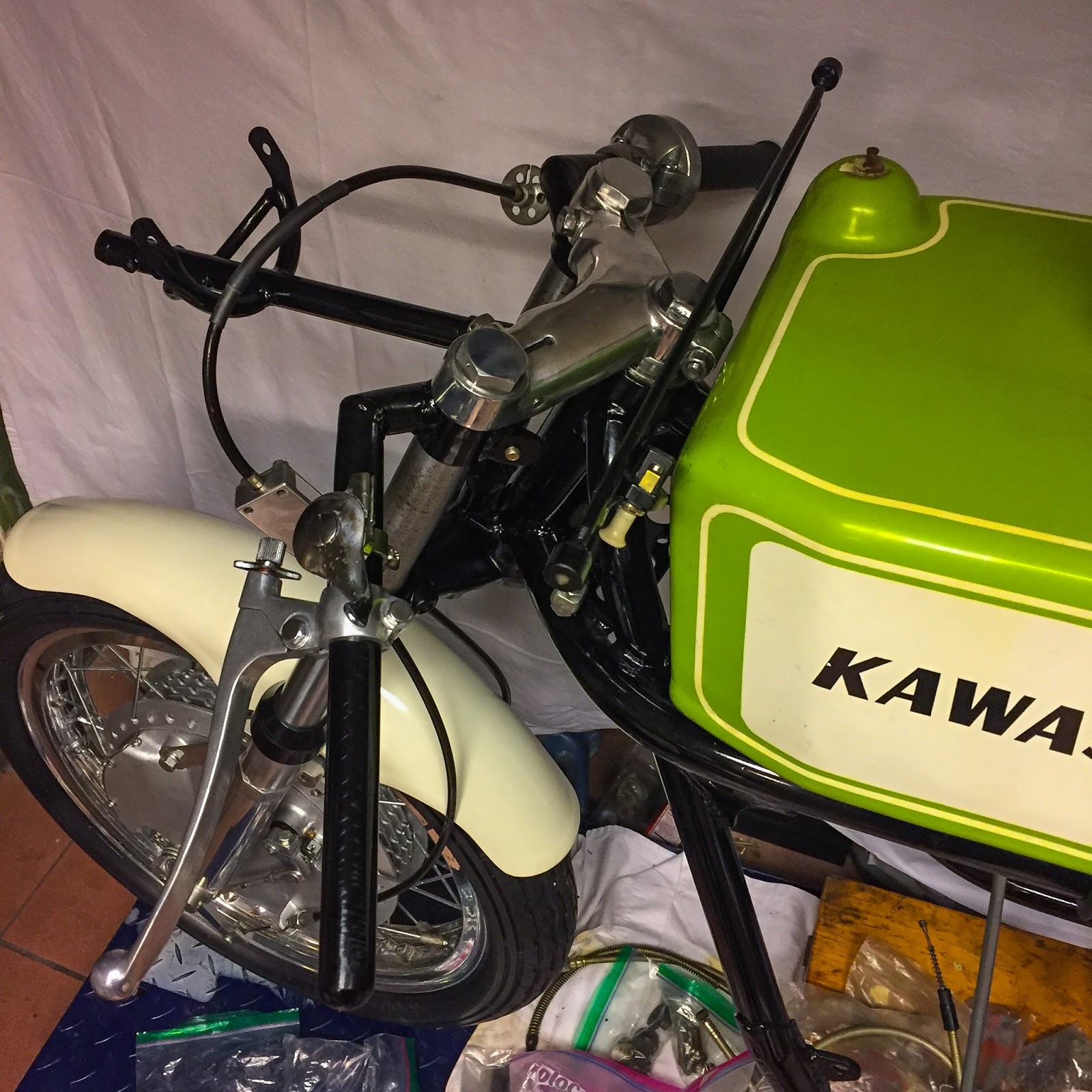
The engine bolts on the bike didn´t look too good. I attempted to search out new ones on eBay and thru a few of my sources over the world. No pleasure. 285mm lengthy, fairly STD, engine bolts. Very particular for the H1R solely and thus unimaginable to search out. Luckily my buddy, Janne, has a big inventory of NOS kawasaki elements and once I had discovered what half quantity I wanted (longer ones with the identical hex head and diameter…) he might discover 3 of them for me!

Within the image on the left you possibly can see the distinction between my “unique” bolts and the brand new one provided by Janne. The three heads on the left simply didn´t work out. Nor did the truth that one in every of them really is nothing greater than a threaded normal rod fitted with some sort of head. Not good! I must get the heads drilled for the security wire, although. We´ll see if I can deal with that myself or if I must get assist.
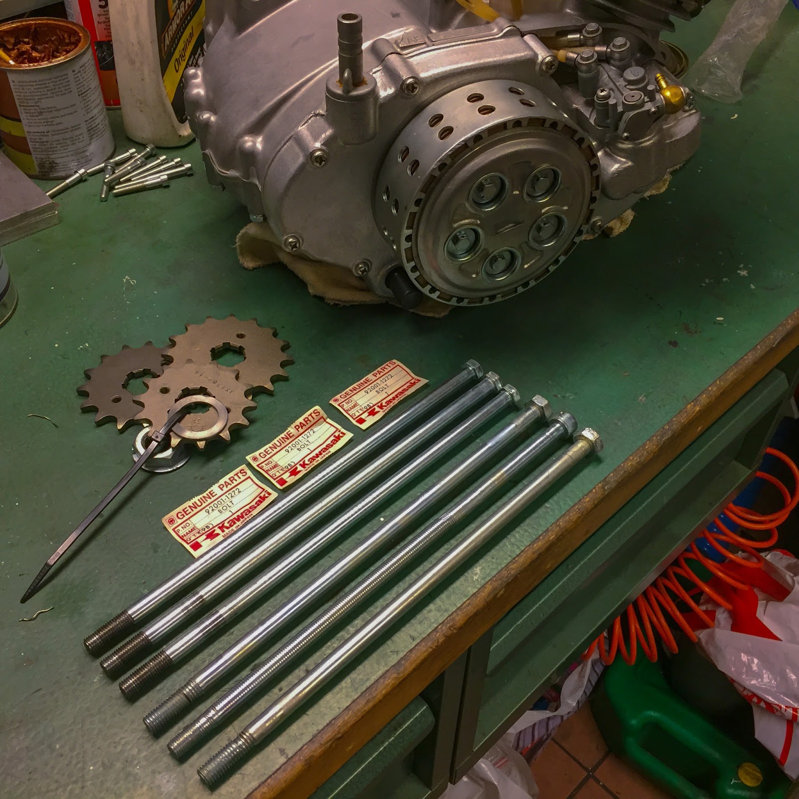
Janne´s good buddy, Wicke, helped me shorten the bolts in his lathe to the required size of 285mm. Half quantity 92001-1272 is an ideal match when shortened by approx 15 mm and threaded some extra. On this image are additionally the elements provided by Ebbe to accommodate a 520 chain and sprockets to the bike. He made the spacer and the particular lock washer wanted to suit these entrance sprockets to the engine. 14,15 and 16 enamel up entrance and three totally different sizes on the again sprocket will probably be fairly sufficient for my racing functions! The rear wheel is at ISR in Tumba right here in Stockholm getting the rear sprockets machined as we communicate! They may hopefully be finished simply after New Yr and are available starting of January I´ll be capable to marry the engine and body in holy matrimony once more! I might threat doing it with out the rear wheel on, however it will likely be quite a bit simpler to do if each wheels are in place.
Tomorrow I´m off for work once more. If I´m fortunate the primary seat cowl from Pär have arrived once I get again. Hold in there for extra, girls and boys!
Glad Holidays and a really Glad New yr to you all!!
/Per.
[ad_2]