
[ad_1]
There´s a “spark” of life….
I actually don´t like doing electrics and ignition methods. I suck at it, huge time.
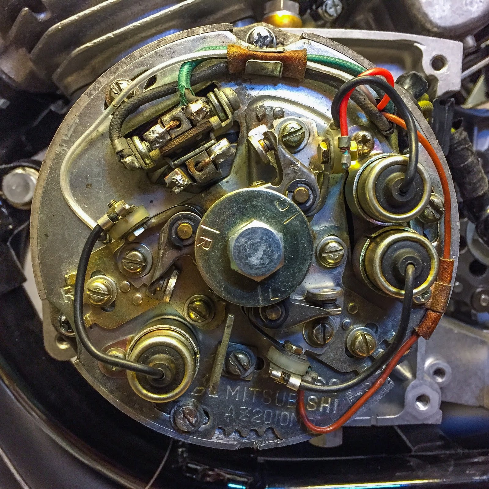
So, higher begin out straightforward and attempt to discover out which breaker level serves which cylinder.
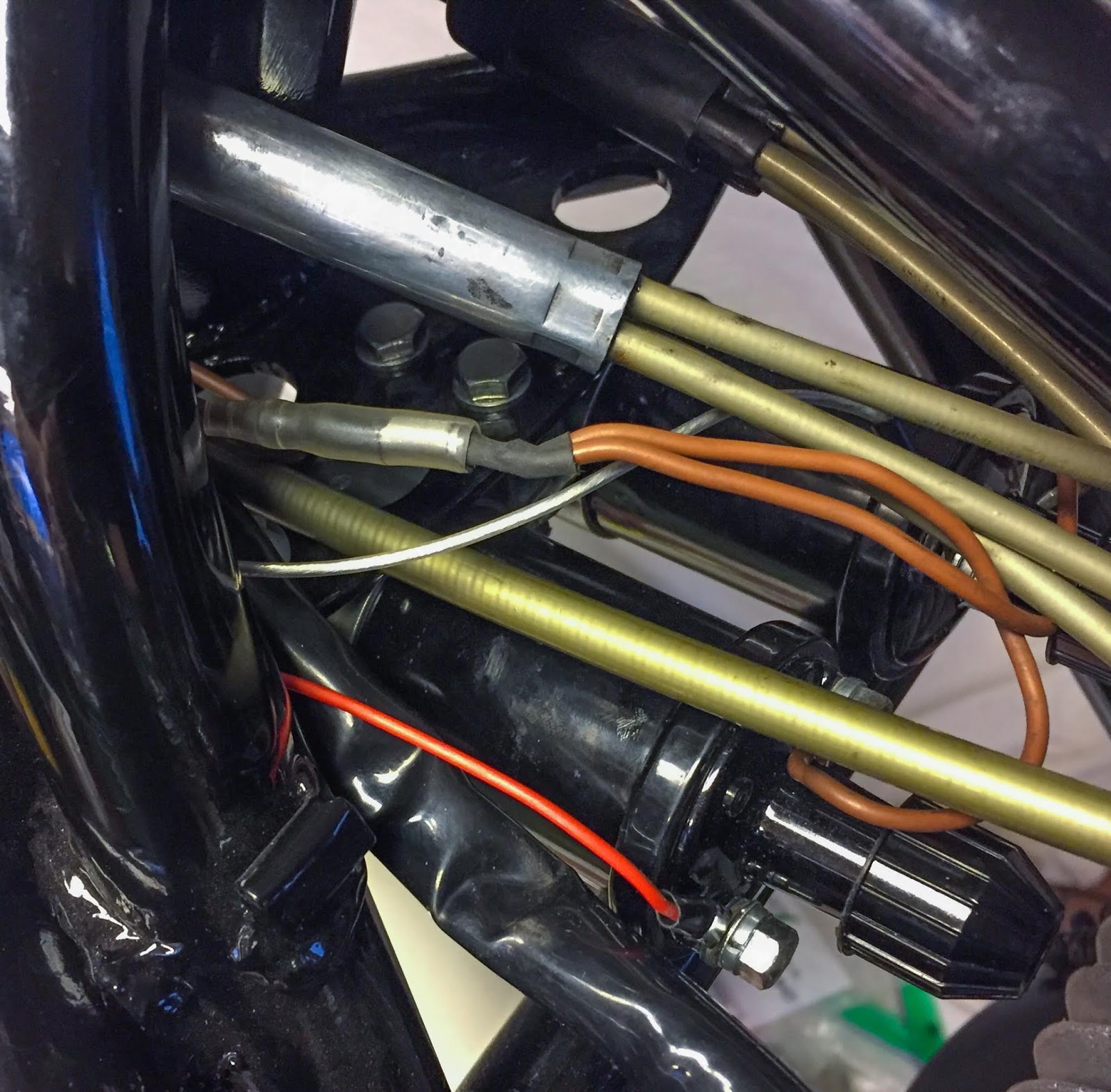
There are three of them, after all. Crimson, White and Brown leads from the factors that connects to the respective ignition coil up on the steering head.
Rotating the engine in its course of rotation reveals the firing order when trying down on the prime of every piston by the spark plug gap.
The course of rotation is well discovered by placing the engine in gear and barely rolling the rear wheel within the appropriate course and observing how the engine turns on the ignition timing plate.
Counter clock smart.
When one of many pistons reaches its TDC (High Lifeless Heart) you merely take a look at the timing plate and discover out which breaker level is about to, or simply opened.
OK, the Crimson lead was for the Left cylinder, the Brown one for the Heart and the White for the Proper one.
First step was merely accomplished when the leads have been linked to its respective coil.
For the reason that coils are all NOS I figured I may preserve the brown provide traces intact on the coils and simply exchange the colour coded ones with my breaker level leads. Simple sufficient!
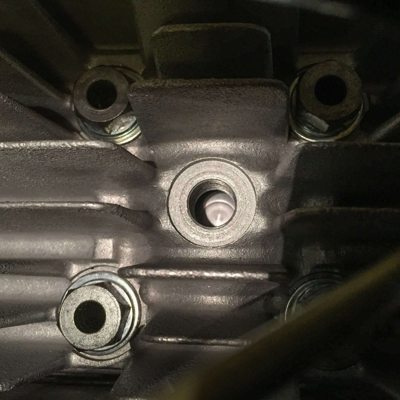
Subsequent was getting the timing appropriate. The handbook says 3,45 mm Earlier than TDC or 25 levels of rotation. I don´t have any tuning protractor however I do have a TDC measuring software.
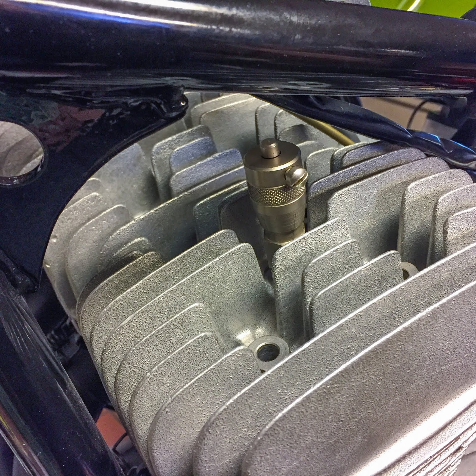
This machine is screwed into the spark plug gap and simply finds the precise TDC and in addition 3,45 mm BTDC.
Right here´s the way you do it.
Unscrew the measuring software at the very least 3,45 mm (there´s a micrometer scale on it), discover TDC by rotation the engine forwards and backwards simply across the TDC and fasten the pin of the software precisely at TDC.
Flip the engine far sufficient backwards, flip the micrometer reduce in precisely 3,45 mm into the software and preserve it there.
Now, rotate the engine slowly, within the course of rotation till the piston hits the measuring software. That is the purpose (3,45 mm BTDC) the breaker level is meant to start out opening, IE the spark plug sparks!

It is usually the purpose the place you set the ignition timing index. On the left right here that is completed and as you possibly can see it aligns fairly good with the Left cylinder index. That’s wonderful since I had the software within the left cylinder. This was one of many issues that had me apprehensive utilizing H1B parts. Fortunately I managed to search out the proper ignition cam and the proper timing cam plate for the H1R. In any other case this might have been extra of a nightmare than it was.
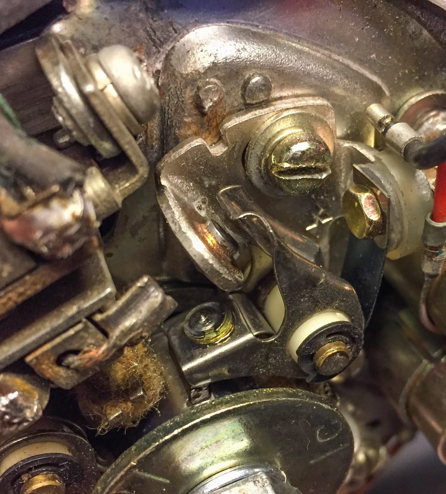
That is the place I had made the primary mistake. I had beforehand adjusted the breaker factors so the cams have been resting on the rotating ignition cam.
Mistaken.
That made the timing inconceivable to get proper. The opening of the factors have been method too huge and that additionally threw the timing out the window.
I needed to begin with the breaker level opening….
0,3-0,4 mm. That meant I needed to rotate the engine and set every level so the utmost opening ended up at, or near, the 0,35 mm I used to be aiming for.

With that adjustment completed I used to be in a position to appropriately time the left cylinder by turning the entire ignition plate so the breaker factors begin to open precisely when the left piston hits 3,45 mm Earlier than High Lifeless Heart.
A pleasant gimmick to get this totally proper is to have an outdated transistor radio within the storage taking part in. When the factors open and the present flows by the coil there’s a distinctive sound over the radio, at the very least in case your ignition system isn´t shielded for radio interference. And I´m fairly certain this method will not be.
On this case I began within the flawed finish and had no electrical wiring in any respect so no present on the coils. Possibly subsequent time.
The timing of the Heart and Proper cylinder is made in the same method, solely now you don´t want the TDC-tool. You merely use the index, align the following cylinder and regulate the factors to open precisely when the index hits then pointer. The Heart and Proper breaker factors are individually adjusted through their mounting plates on the timing plate.
To verify Ebbe acquired the crank completely mounted with 120 levels separation between the cylinders I checked the three,45 mm BTDC on the Heart and Proper cylinders as properly. Higher secure than sorry!
With a view to get this 100% appropriate it’s a good suggestion to do a dynamic verify utilizing an ignition timing stroboscope when the engine is working. Possibly later…

No spark with out electrical wiring. Subsequent was getting the parts linked and wiring drawn.
I’ve had some dangerous experiences with poor floor messing issues up attempting to start out a number of bikes over time. Higher do it proper this time.
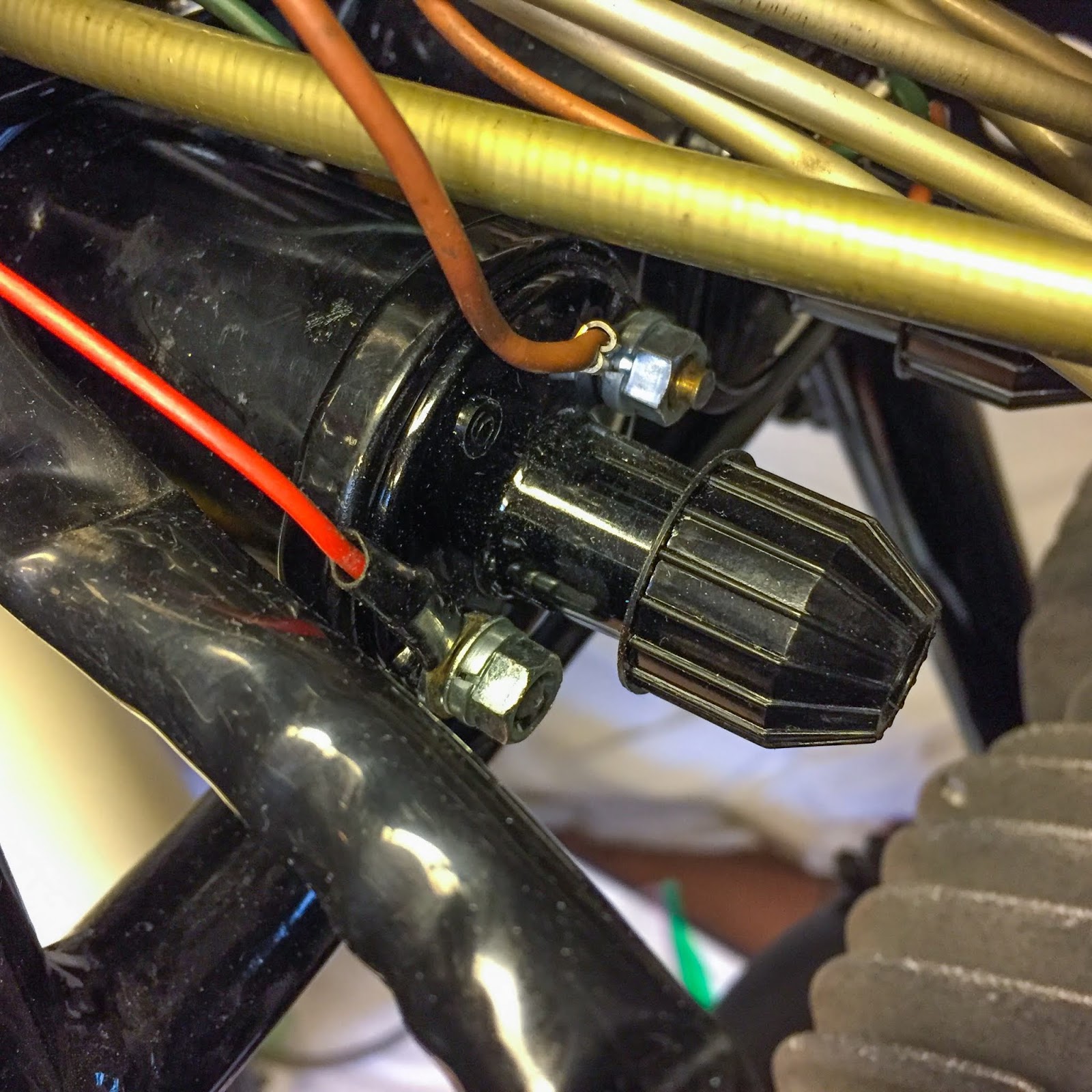
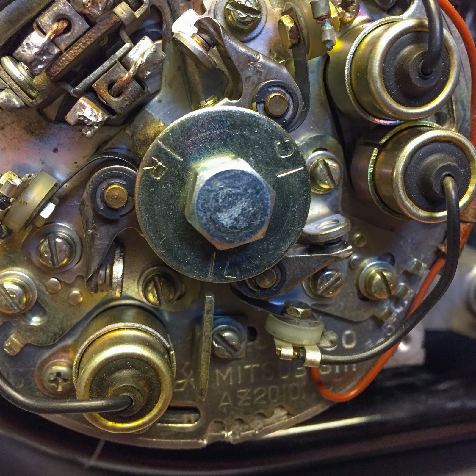
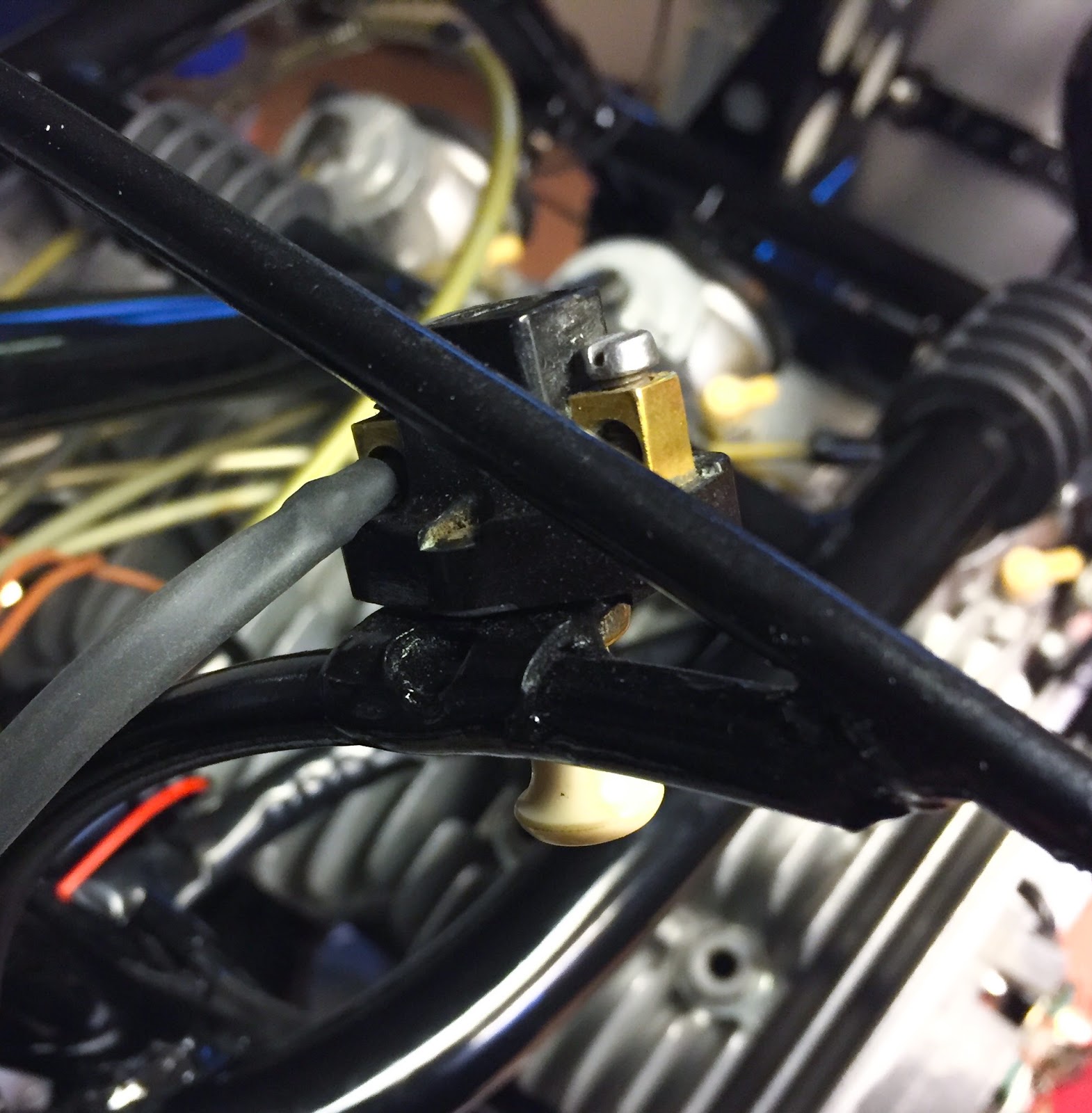
The rectifier (on the precise within the image) is meant to be grounded on the mounting level. I couldn´t be certain the entrance cowling keep (the “spear”) was grounded ok by the mounting bolts. Paint generally is a ache in terms of grounding parts.
The regulator, on the left within the image, doesn´t should be grounded so no want for any further wires there.
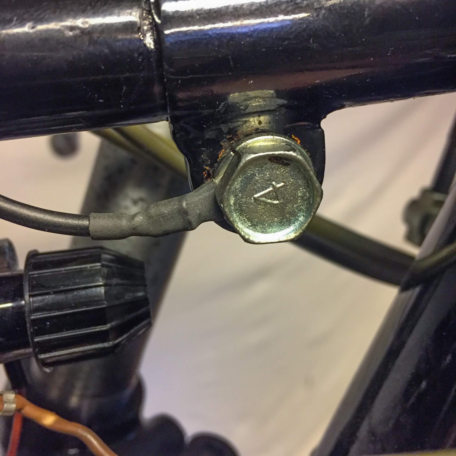
So, I made an additional floor wire to make sure. That is the “spear” mounting screw with the brand new floor wire linked to it. Within the final image you would see the opposite finish on prime of the rectifier.
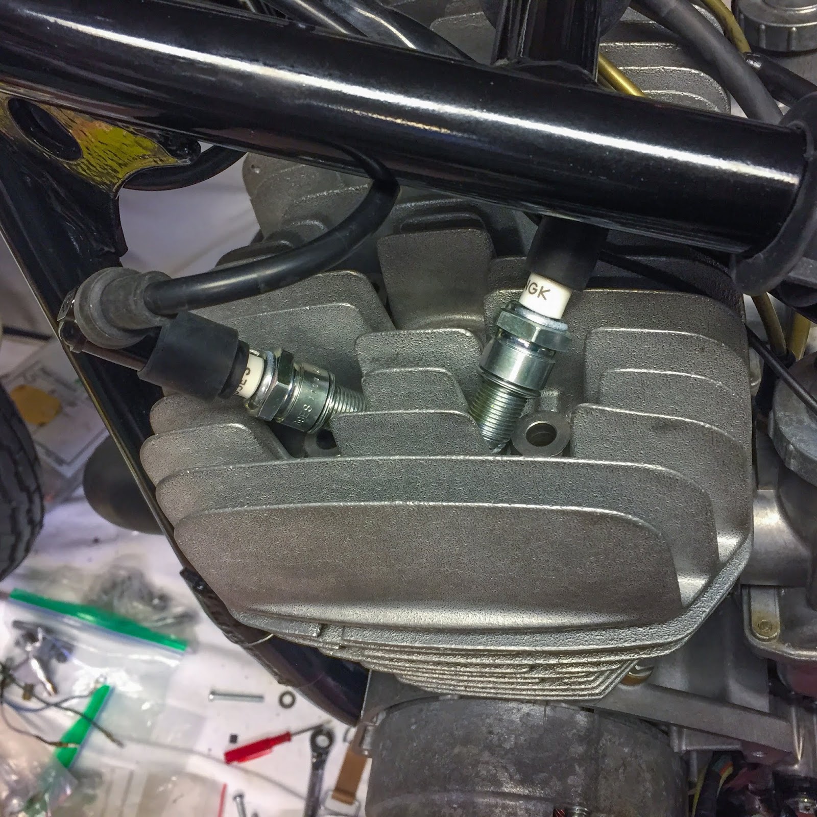
On this image we are able to see the ignition coil and the fastener for the excessive stress wire. On H2:s the excessive stress cords are built-in with the coils, however right here they’re replaceable. I do have a plan for what sort of cords to make use of. We´ll discuss that in a while.

Connecting the parts right here was truly fairly straightforward. Coloration coding labored to 90% and the final 10% was simply discovered through the wiring diagram within the handbook.
The Brown one from the regulator and the Crimson one from the rectifier shall each be linked to the Ignition change. The rectifier, Crimson one, scorching wired to the battery and the regulator, Brown one, over the ignition change.

Three Brown wires from the ignition coils along with the Brown one from the regulator to the switched facet of the ignition change.
It took some determining how to do that one of the simplest ways. I although I had some good three-way-bullet-connectors in inventory, however no, I didn’t. Higher get inventive, then…

If in case you have the proper elements and instruments, making wiring is definitely fairly a little bit of enjoyable, upon getting found out the way to join the elements smartest.
On the left right here is the feminine connector crimped to the wire. These “bullet” connectors are used on all Japanese bikes and are available at many venues over the web.
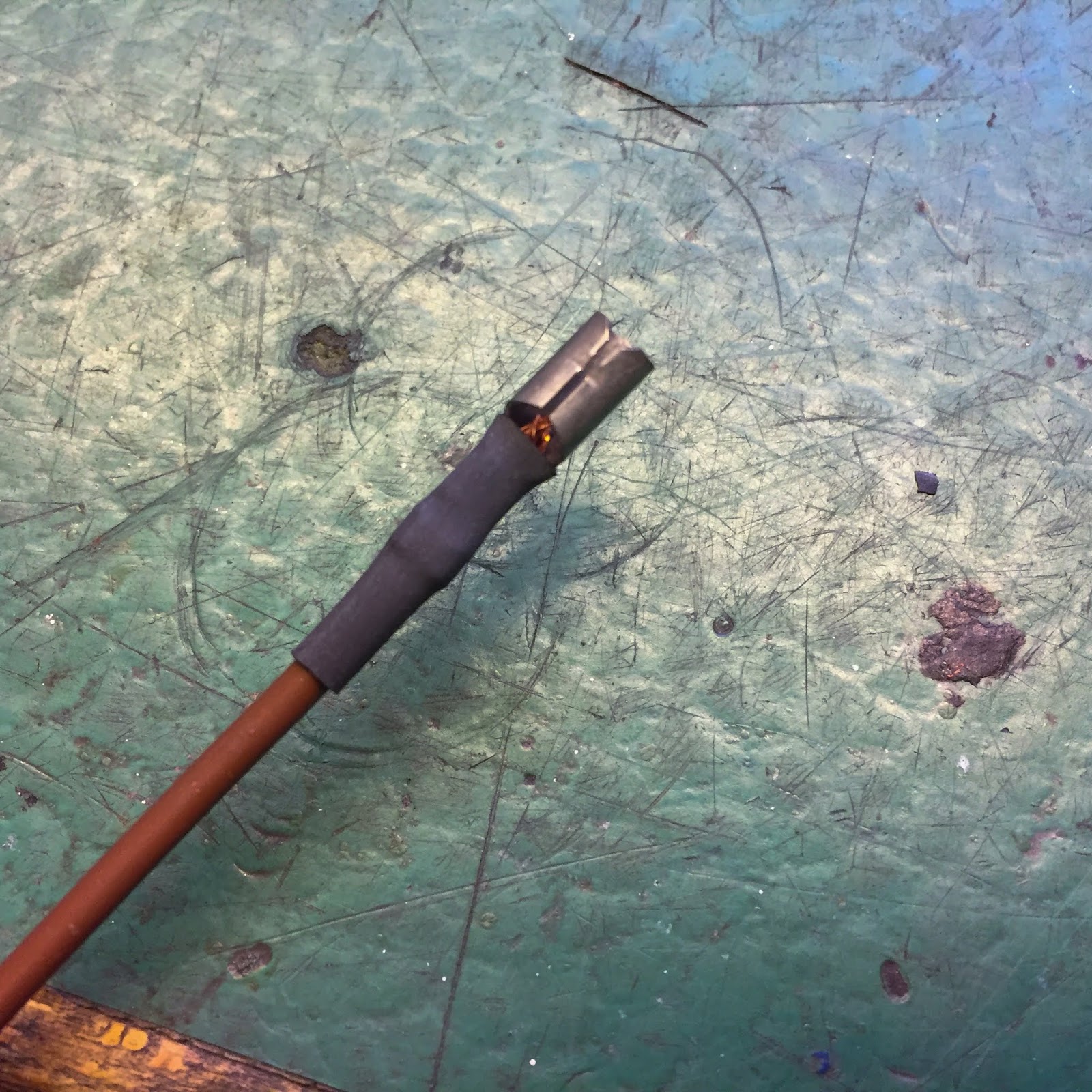
Subsequent is the shrink tubing. This seals the connector from the weather and retains water and filth off the crimped half.

Lastly the protecting clear rubber cowl is connected and the connection is finished!
Simple peasy.

Since I didn´t have any three-way connectors I fastened it one other method. Two wires in to 1 bullet connector. Not optimum, nevertheless it´ll work out superb.
That appears ok for me. The target right here was merely to get present from the ignition change to the coils and regulator. Executed!
That completes the switched facet of the circuit. A little bit of shrink tubing and one other bullet connector barely modified to suit the ignition change and it was time to maneuver on to the unswitched facet of the system.
That was simply completed. I merely needed to pull a wire from the battery to the change and join one other result in the “scorching wired” rectifier.
Electrical system linked and constructed. Will I ever dare to attach a battery and flip the change? That, my mates, is a totally completely different ballgame….
I discussed the excessive stress cords earlier. My plan was to make use of those provided with the H1B coils. They’re NOS, they’re Kawasaki unique spec merchandise and I believed they might match. In addition they have these good “L”, “R” and “C” labels on them. Looks like a pleasant contact. The one drawback was that one in every of them, the “C” one was method too quick.
On the H1B the coils are all mounted beneath the tank and the middle coil is fixed proper above the middle spark plug. On the H1R the middle coil is mounted far up entrance on the “spear”. I had to make use of one other wire quickly. Within the meantime eBay was consulted and a model new H1B/A7/A1 excessive stress wire was situated and purchased from Wisconsin, USA.
At this level I had been engaged on the bike a full day doing a lot of different stuff as properly, however I couldn´t resist testing {the electrical} system and verify for spark. On reflection I ought to have waited and thought issues by a bit extra…
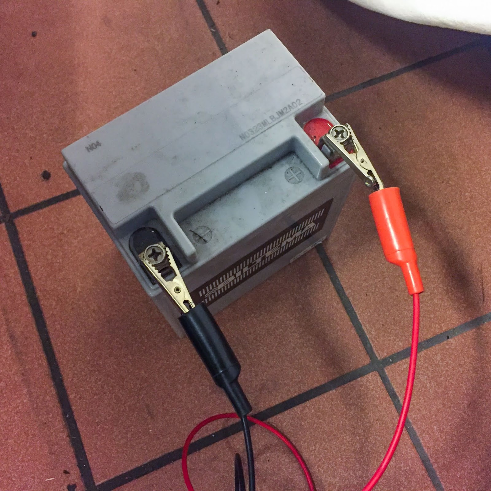
Connecting the system to a battery was straightforward sufficient. A properly charged Z1 battery would most definitely do.
These flimsy “jumper cables” will probably be superb. There´s no starter right here that wants a giant amp output so this can work.

And the connections on the battery field. Higher verify fastidiously that the plus terminal doesn´t are available in contact with the body or the damaging terminal. We don´t need any quick circuits right here!
Actually nervous after I pushed the change in to change the ignition “ON”. Wouldn’t it blow the fuse, begin a hearth someplace?
No, nothing occurred, and that´s good! Now, A delicate spin on the rear wheel… Nothing.
No spark, no sound, no nothing!
GAH!! I knew this might occur… Nicely, I pulled the change out and for some cause tried spinning the rear wheel. Sparks on all three! What??
I measured and checked the whole lot again and again and got here to the conclusion that I did have spark on the system when the ignition change was turned off and there was no present on the coils…
I used to be drained, it was the final night time earlier than going off to work so I made a decision to depart it proper there. I wanted time to assume this by and look fastidiously on the electrical wiring methods for the H1R and the H1B.
OK, pleased to have spark? You guess! However why when the change was off….?? I had some considering to do in the course of the weekend I used to be off working.
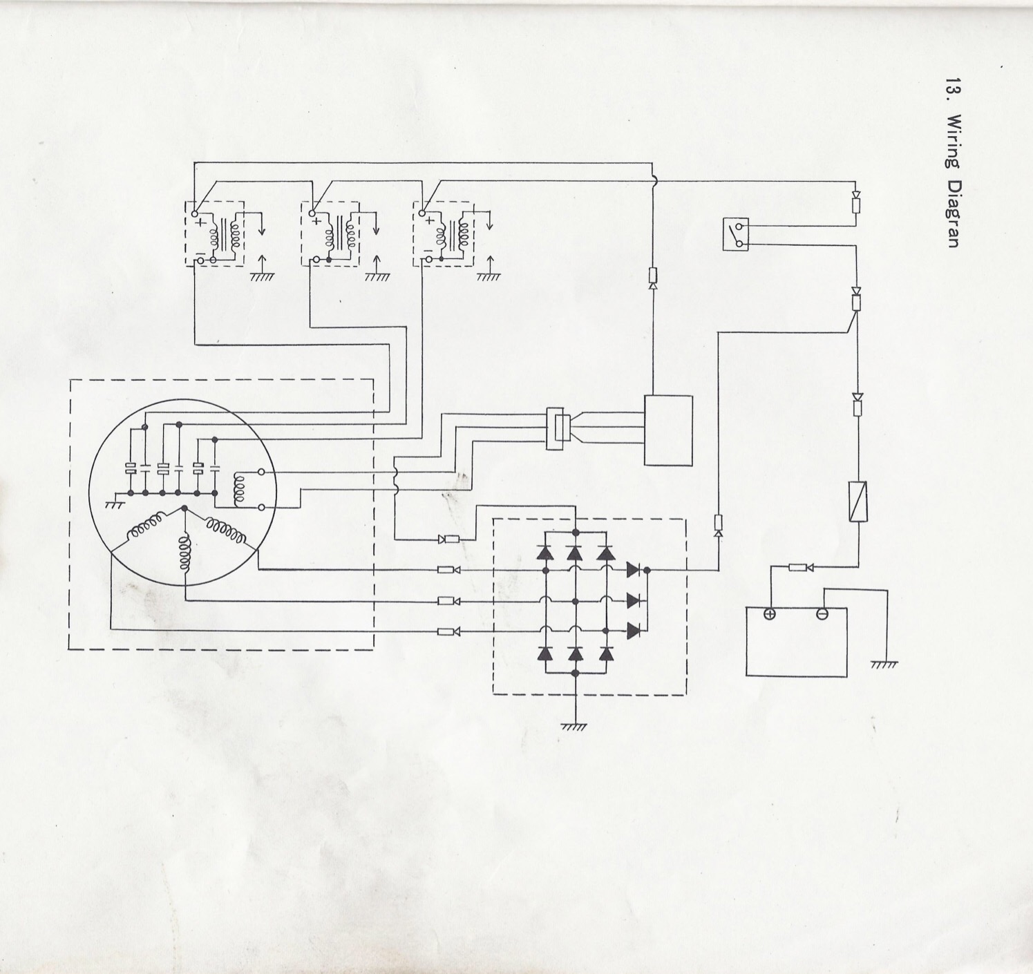
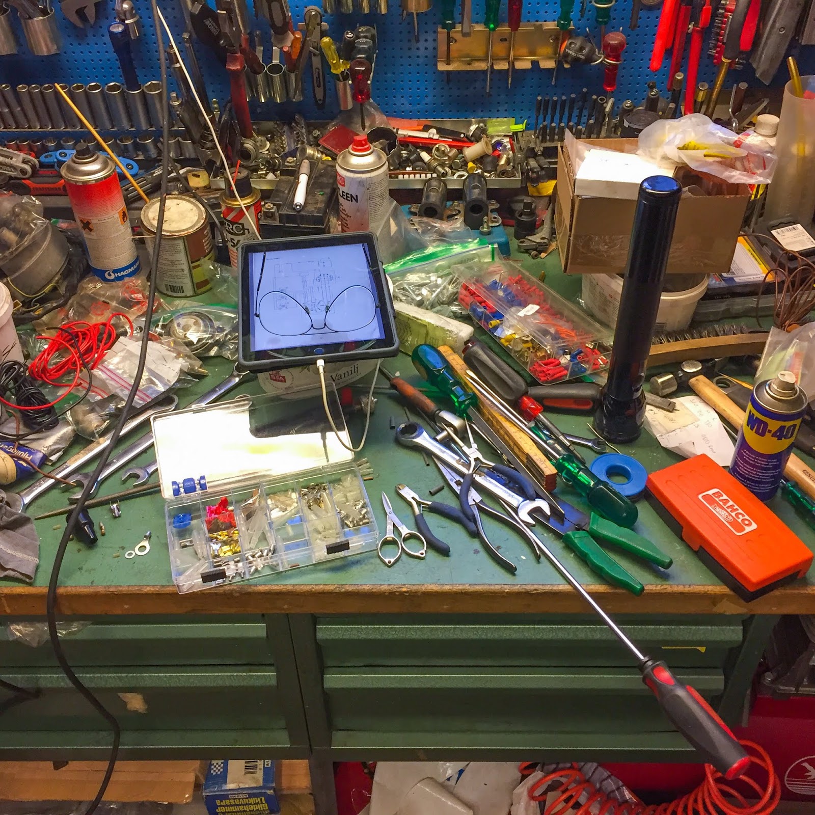
I’ve the H1R wiring diagram in my iPad and introduced that to work to assume issues over. How arduous can or not it’s?
I had completed all connections in accordance the schematic and nonetheless that unusual phenomena.
May or not it’s one thing completely different with the H1B coils versus the H1R:s?
It’s easy sufficient to see that the coils want present on the optimistic terminal by the ignition change. How does it look on the H1B diagram?

Kind of an identical diagrams other than the truth that the road bikes have a lot of different issues occurring within the system, like lights, extra sophisticated ignition change, flip indicators and brake lights and so on, and so on… However the similarities in regards to the regulator, rectifier and the present to the coils are very actual. these schematics all through that weekend was driving me kind of loopy.
Lastly I noticed I will need to have gotten all of it flawed there, that late night time, being drained and over enthusiastic having accomplished the electrical system.

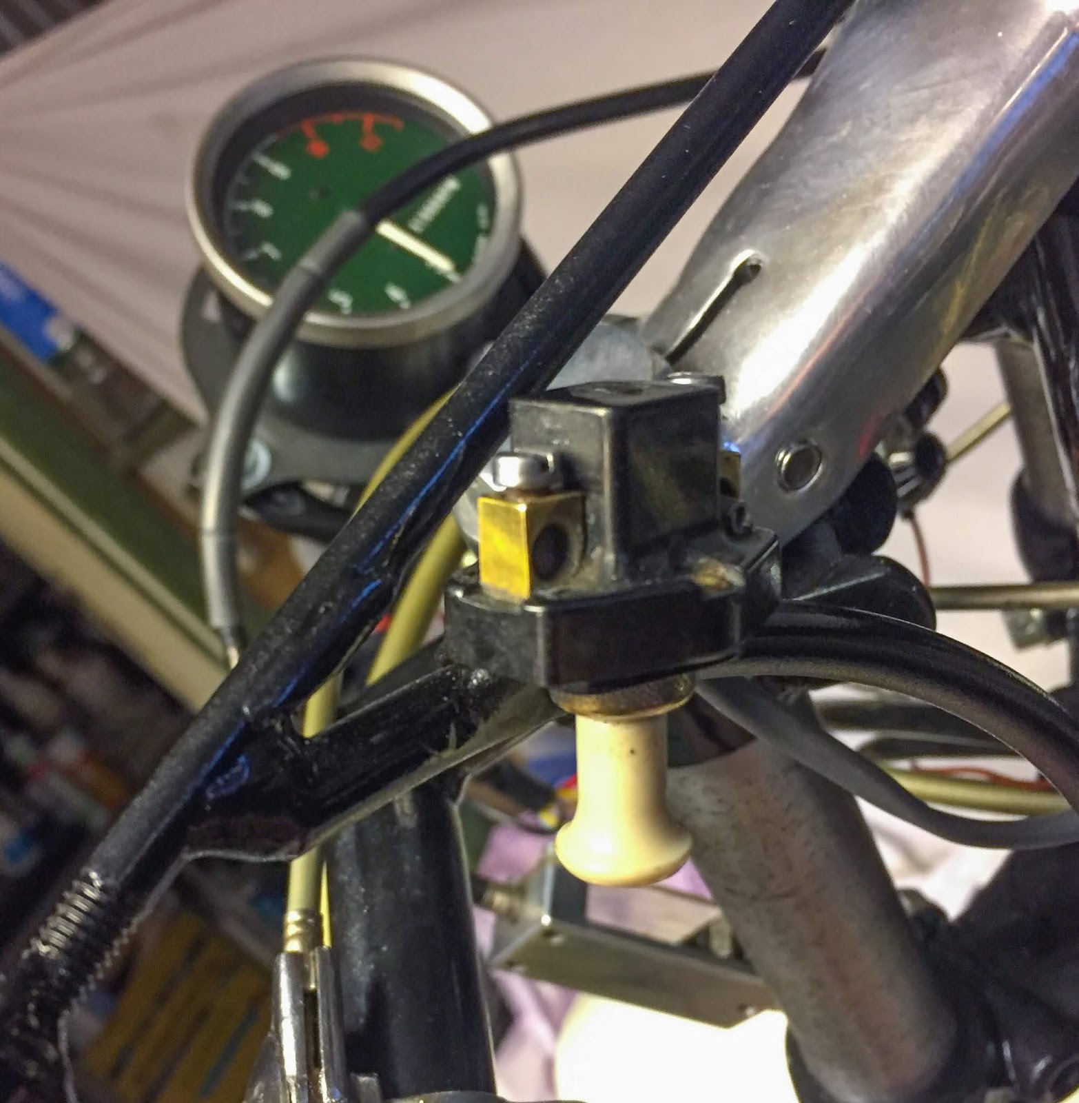
The very first thing I did after getting back from work was hitting the storage and checking the ignition change…
Yeah, You guessed it. The change is “ON” when pulled out and “OFF” pushed in.
In my deranged frame of mind that late night I made many errors together with the great achievement to get a easy voltage verify over a circuit breaker all flawed ending up spending a full weekend considering over one thing that was appropriate on a regular basis. Fortunately I didn´t do one thing silly, simply left it on the carry and went to work…
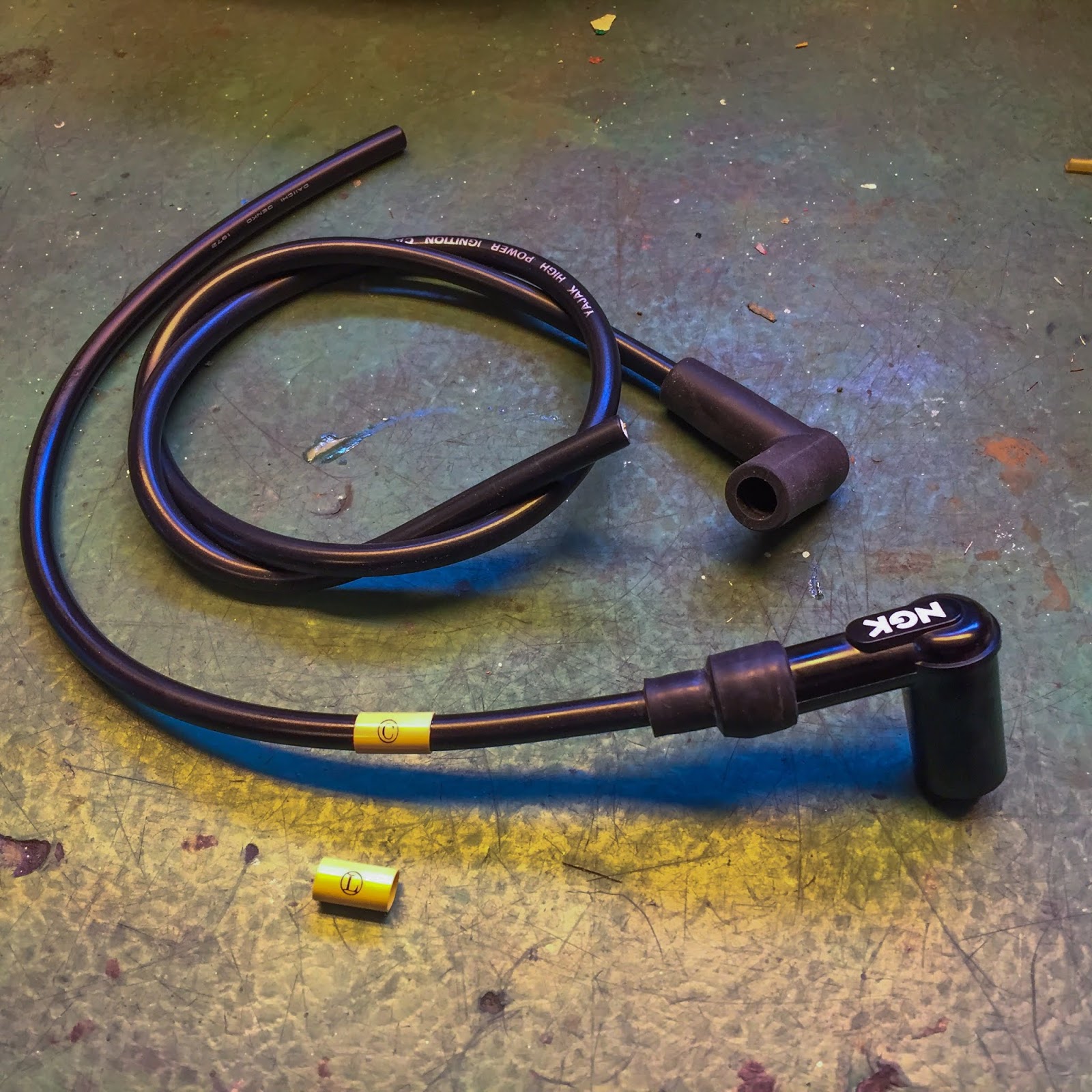
Just a few days later the lengthy excessive stress wire arrived and I may exchange the non permanent one with a extra unique trying wire.
Seen right here on the precise with the “C” label ready to be connected. These NGK spark plug caps must do for now. The unique H1R (21130-015) are, after all, inconceivable to search out. I do have a plan for one thing extra inventory trying, although.

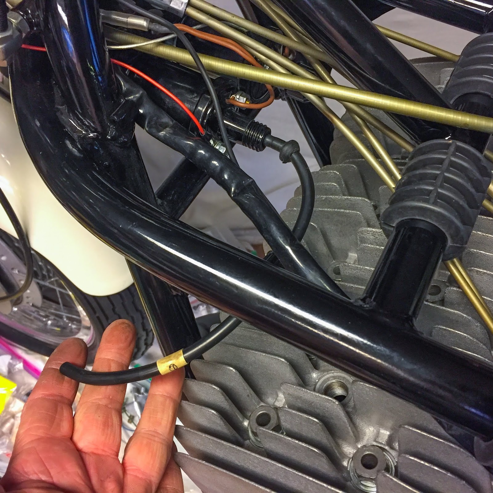
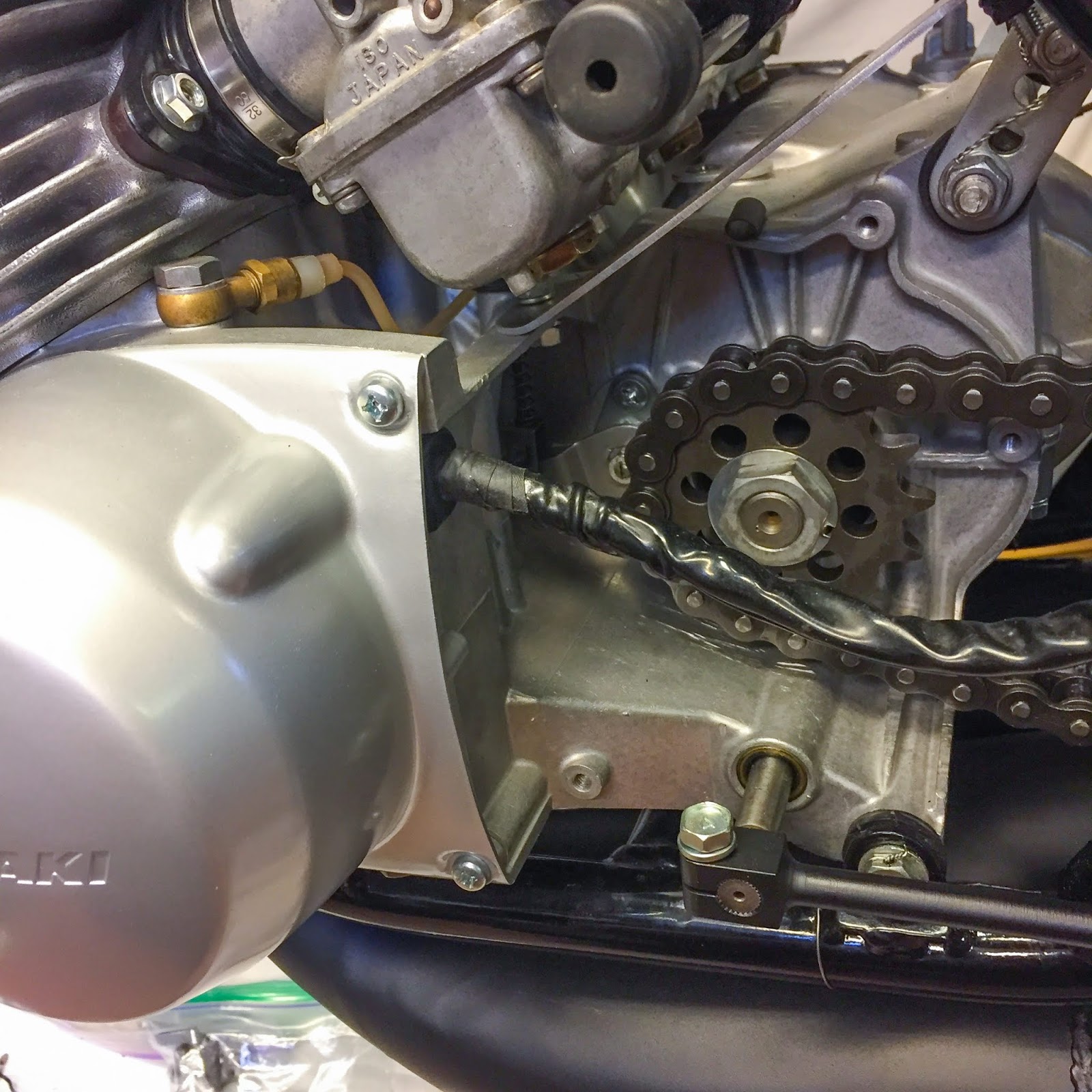
Now that the wiring was all completed it was time to place the wiring loom in place on the body. As I mentioned earlier, the loom is fairly lengthy and I needed to make a loop of it because it exits the ignition cowl. My plan was to tug it up beneath the carburetor, over the chain cowl after which up in direction of the steering head. Not good.
It needed to be like this within the image on the left. outdated photos and images of different H1R:s around the globe I discovered that that is the way in which they’re mounted. It’s also possible to see the black lead on the body tube going to the battery.
I had a few choices concerning fastening the wire loom to the body. I had some inventory wire loom bands used on the H2:s and the older rubber kind used on the A1/A7:s and actual early H1:s. None of them seemed proper. In outdated pics it seems to be like it’s merely taped with electrical tape to the body. Simple sufficient, however I couldn´t have it that method.
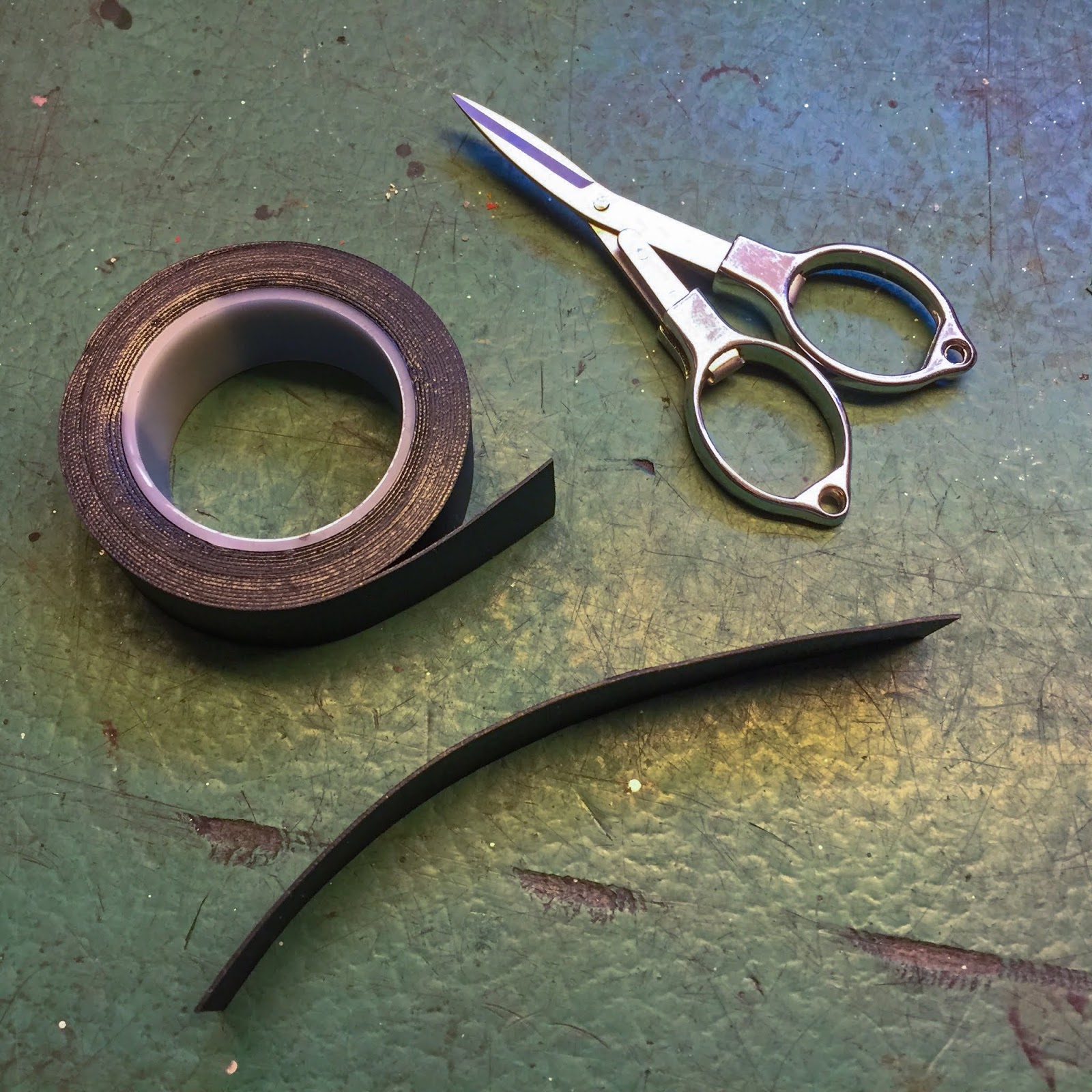
The answer? Vulcanizing tape!
An exquisite product I’ve used on many events by the years. It seems to be like easy electrical tape however varieties a stable rubber tube when stretched about 50% after which utilized in as many layers you want. It’s even attainable to manufacture O-rings with these items. I believe its major objective is repairing cooling tubes on automotive purposes and so on.
I changed the electrical tape on the loom exiting by the ignition cowl. A lot tighter and a greater seal than the atypical tape.

To the precise right here I´m making the rubber fasteners for the loom. The loom sits on the within of the tubing and 4-5 turns with the vulc tape stretched to approx 50% acquired it completed!

I believe it seems to be very real and a bit like that flimsy electrical tape from the outdated days. I really feel quite a bit higher about this technique although. It gained´t come off simply!
I believe I´ll exchange additionally the H2 bands holding the battery lead. I´ll repair that in a while.
What else wants fixing?
The entrance brake… I by no means adjusted it correctly, merely put it collectively.
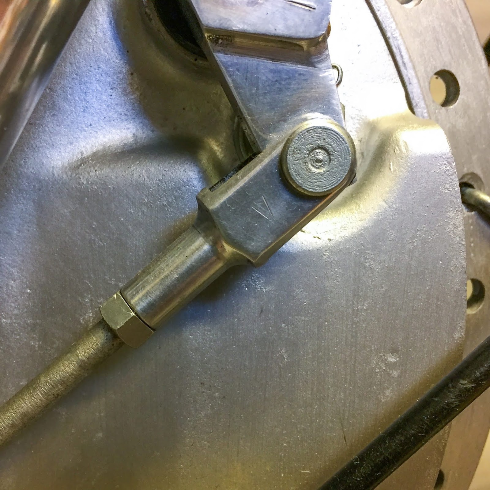
I used to be planning to safe-wire these screws holding the entrance brake torque arm to the brake plate. Janne had some good lock washers helpful so why not? Lets attempt them on.
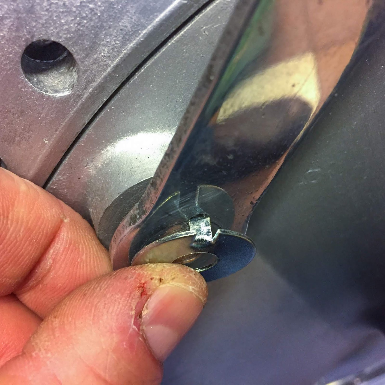
As you possibly can see they wanted some adjustment additionally. Tab too broad and gap too small. I believe they’re unique on the Yamaha TZ:s they usually clearly use 8mm screws and Kawasaki 10mm.
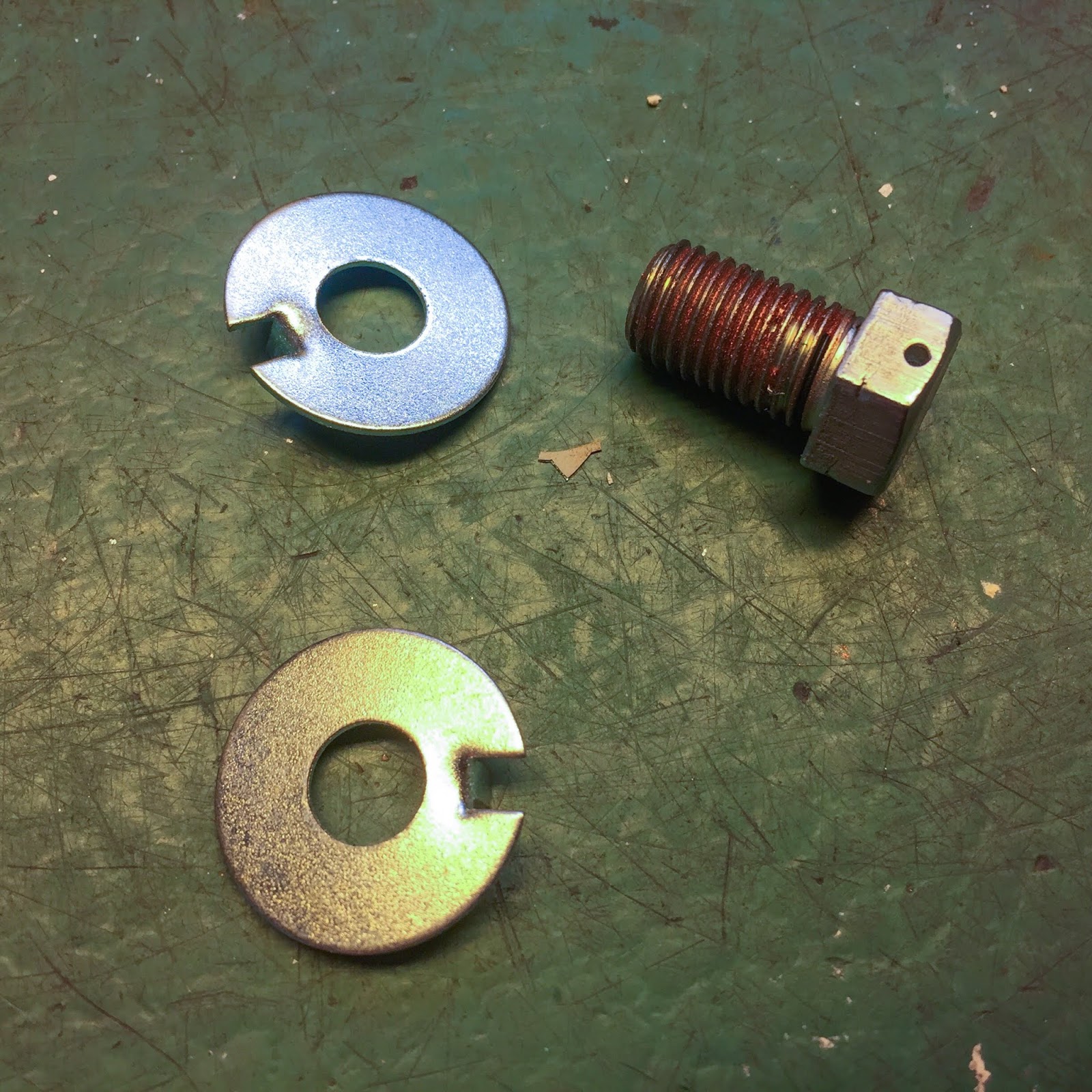
Nicely, not too tough modification to do. Slicing the tab and submitting the opening up a bit. The drilled gap within the screw head tells it was safe-wired earlier than. For now, I´ll go along with this resolution. I believe it seems to be higher than the wire.
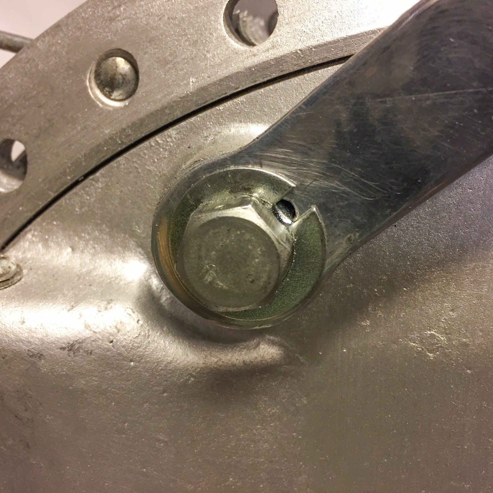
Completed! Apart from the ultimate bending of the washer to the screw head. Nicely, by now, I all the time do the whole lot at the very least two occasions… Higher go away that to the very finish of the construct when all is finished and examined.

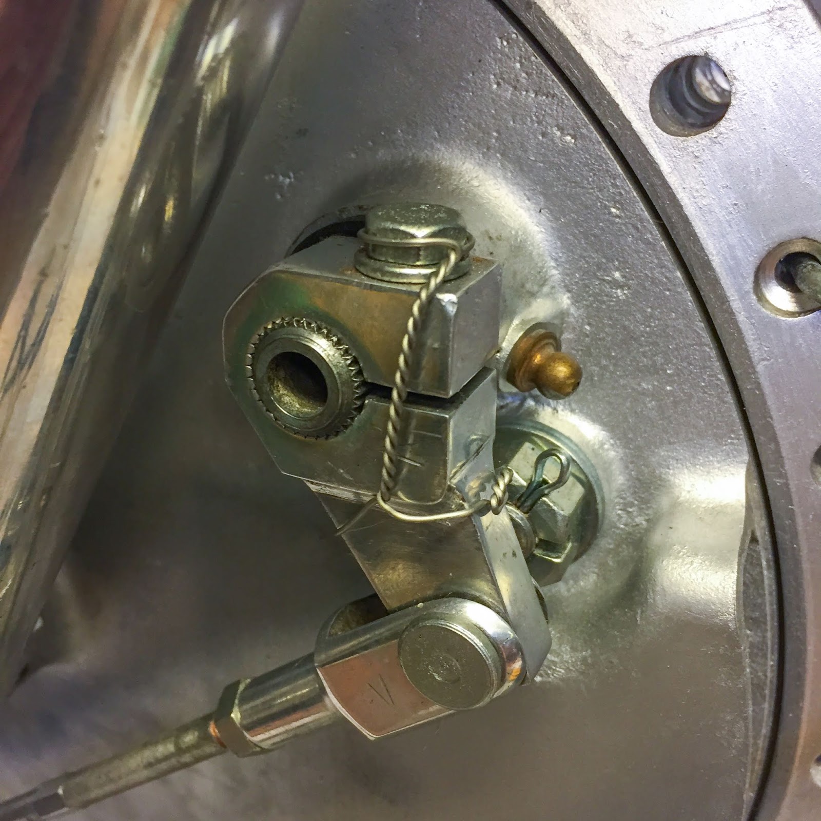
Adjusting the entrance brake is finished in a few completely different steps. The concept right here is to have each brake linings on both sides contact the drum concurrently. Every lining on both sides is moved by one brake lever on the brake panel. They’re linked with an adjustable rod. The tactic is easy sufficient.
Regulate the connecting rod as quick as attainable to verify the rear brake lining doesn´t contact the drum when the massive lever is pulled by the brake deal with up on the deal with bar.
On the left right here I’ve adjusted the connecting rod. discover the distinction in angle between the massive and the small lever. It’s fairly clear that the rear (small) lever is not going to transfer the liner in direction of the drum earlier than the massive one.
The subsequent steps require the chance to rotate the wheel freely. Okay, I´ll have to repair that first!

Tough one… I couldn´t use a jack beneath the engine since I already had the exhaust on (see my level about all the time doing issues at the very least two occasions….!!)
I ended up placing a big hook up on the ceiling. Fortunately I had famous the place I’ve the beams beneath the drywall ceiling…
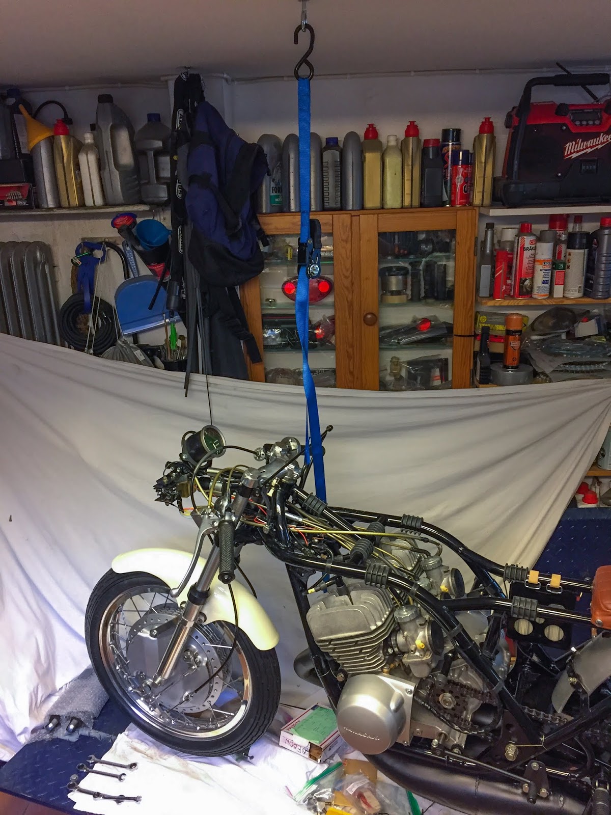
An ideal match proper above the steering head. A ratchet tie-down and up the entrance finish went!
Right here it’s hanging from the ceiling and resting on the stand on the foot pegs. Labored like a allure!
I have to share this video of the entrance wheel spinning freely…
Think about it’s a 50 12 months outdated wheel. I believe it spins very good. The slight wobble seen on the tire might be because of the tire being empty. I´ll check out that later after I´ve crammed it up.
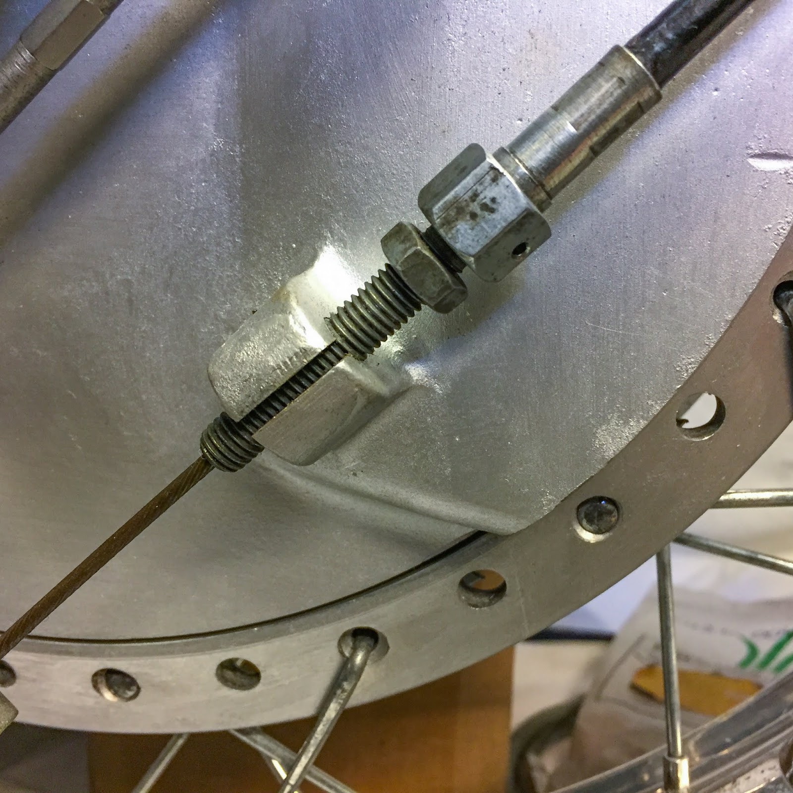
The adjustment begins with the massive lever on the plate, the one actuated through the brake cable. I began out with unscrewing the brake cable adjuster till the entrance brake ling began touching the drum. Then backed of till the wheel may spin freely once more.
Subsequent was the small lever (rear brake lining).
Wile slowly spinning the wheel you regulate the connecting rod till the rear ling touches the drum. On this place the rear lining will hit the drum first. Not good. Again it off till the wheel turns freely once more.
Now you’re shut!
The ultimate take a look at is to tug the brake lever on the deal with bar and verify that each linings contact on the identical time. That is completed by fastidiously adjusting the connecting rod till the free play is gone on the rear (small) lever. It sounds sophisticated however it’s fairly straight ahead when you consider it.
When your completed on either side, the slack within the brake cable gained´t be too huge and hopefully the adjuster up on the brake lever will be capable to take it out with a margin to spare for adjusting the brake throughout using with fading brakes..

Time to get cracking with this buddy once more!
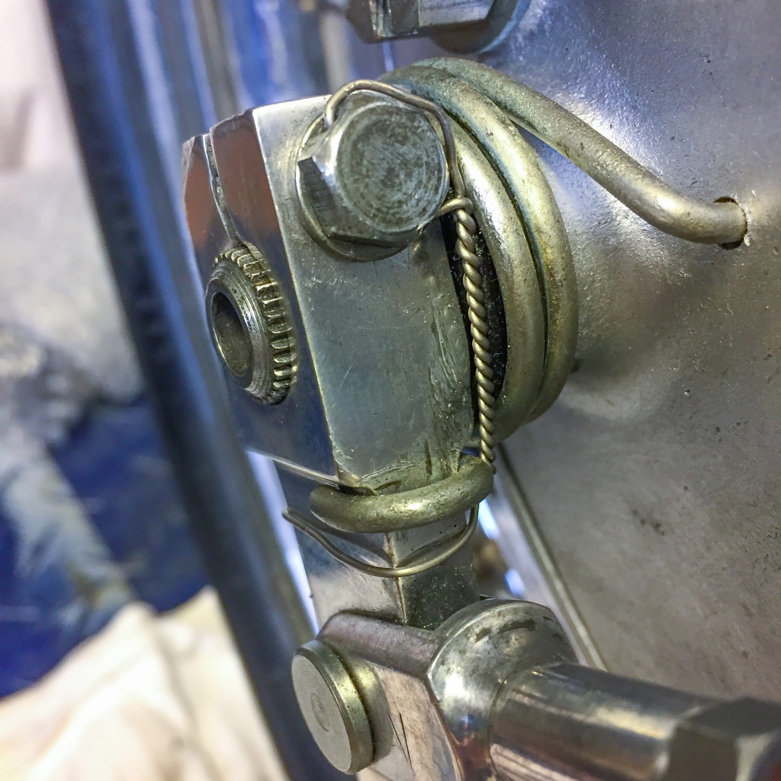
There are many fasteners to safe-wire on the entrance finish of the bike.
I really feel snug doing a few of them now. Some I’ll save for later, till I´m positively sure that exact fastener is not going to need to be loosened once more.
The rear (small) brake lever on the left hand facet brake plate.
The massive one, entrance left brake ling lever. Not good, nevertheless it´ll do…
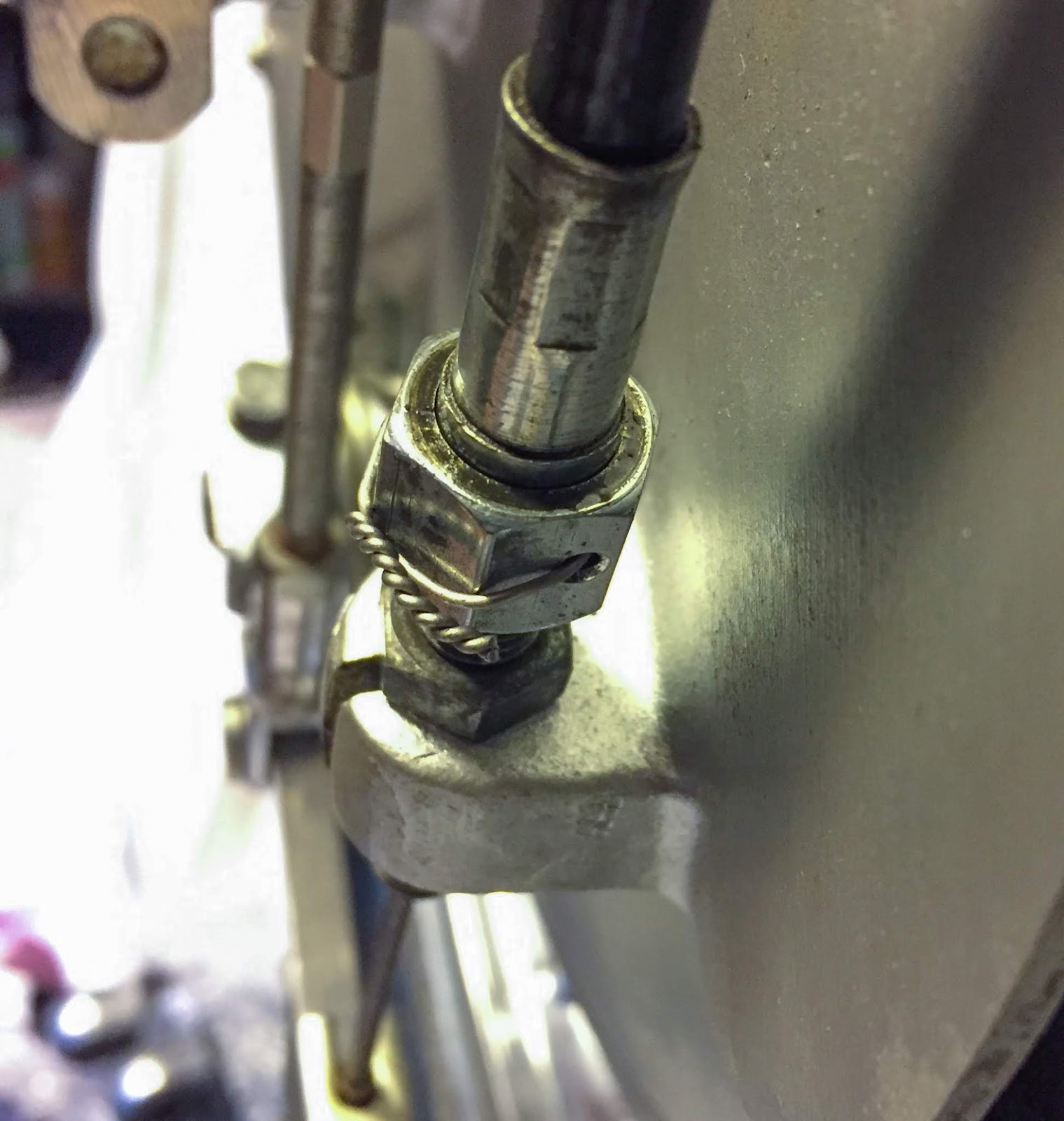
The left brake cable attachment to the adjuster on the brake plate.

The steering head nut and screws. I´m form of happy with this one… Three fasteners with one piece of wire. Okay, I do know, it ought to have been tighter, nevertheless it´ll do for now!

And the highest triple tree pinch bolt. This was the final one this night. I want extra wire!

It’s “Bloody enterprise” restoring outdated racing bikes…
I managed to hit my brow on the rectifier bustling up and down adjusting the entrance brake and safety-wiring the entrance finish. I didn´t discover it when it occurred so this was a pleasant shock after I seemed within the mirror!
And that selfie, my mates, would be the finish of this publish. See you all subsequent time!
Hopefully the aluminium tank is getting completed quickly at Alucars and perhaps I can borrow Janne´s pit starter. Yeah, quickly time for the primary begin try….
Keep secure and preserve the entrance rubber on the asphalt.
Spring is lastly right here!
/Per
[ad_2]