
[ad_1]
It´s on wheels!
I actually acquired impressed getting the rear wheel completed, so I moved on with the entrance one. Getting the brake plates full was the duty of the day. I had all of the components out and sorted them, bear in mind. Properly, it confirmed afterward I didn´t try this completely sufficient. Extra about that later.

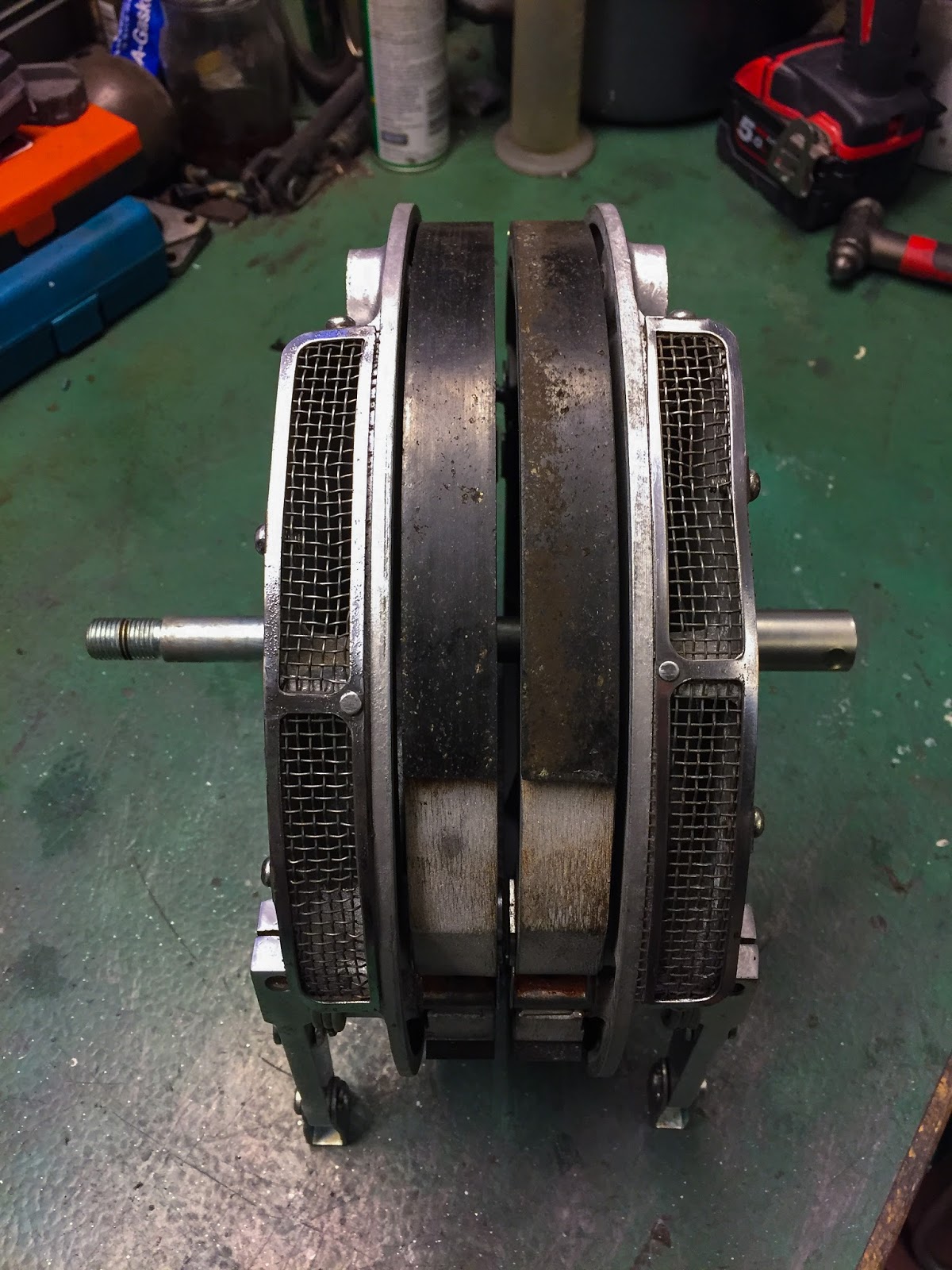
The entrance brakes differ a bit from the rear one. There are two cams, every shifting one brake shoe on all sides, 4LS know-how, up entrance the place there´s just one cam shifting each sneakers on the rear. Meaning two of the whole lot on all sides. Two cams and two shoe pivots. The pivots are fastened to the plate and solely want a lightweight coat of grease or copper paste for the sneakers to maneuver simply. The 2 cams will be greased from the surface and wish extra common consideration. I discovered from the rear to mount these sturdy springs earlier than placing the sneakers on to the plate. With the whole lot greased up and double checked the mounting was pretty straight ahead.
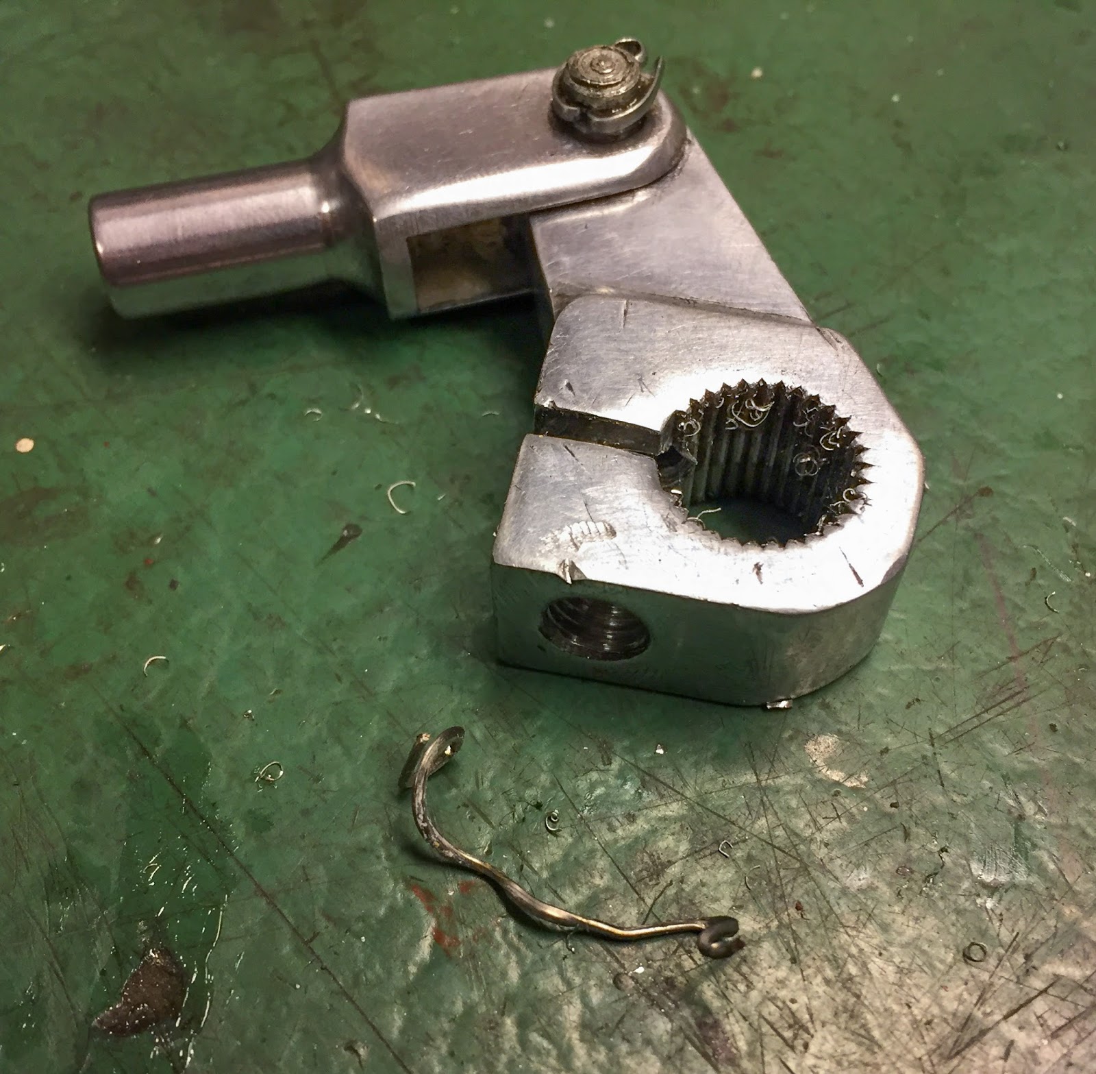
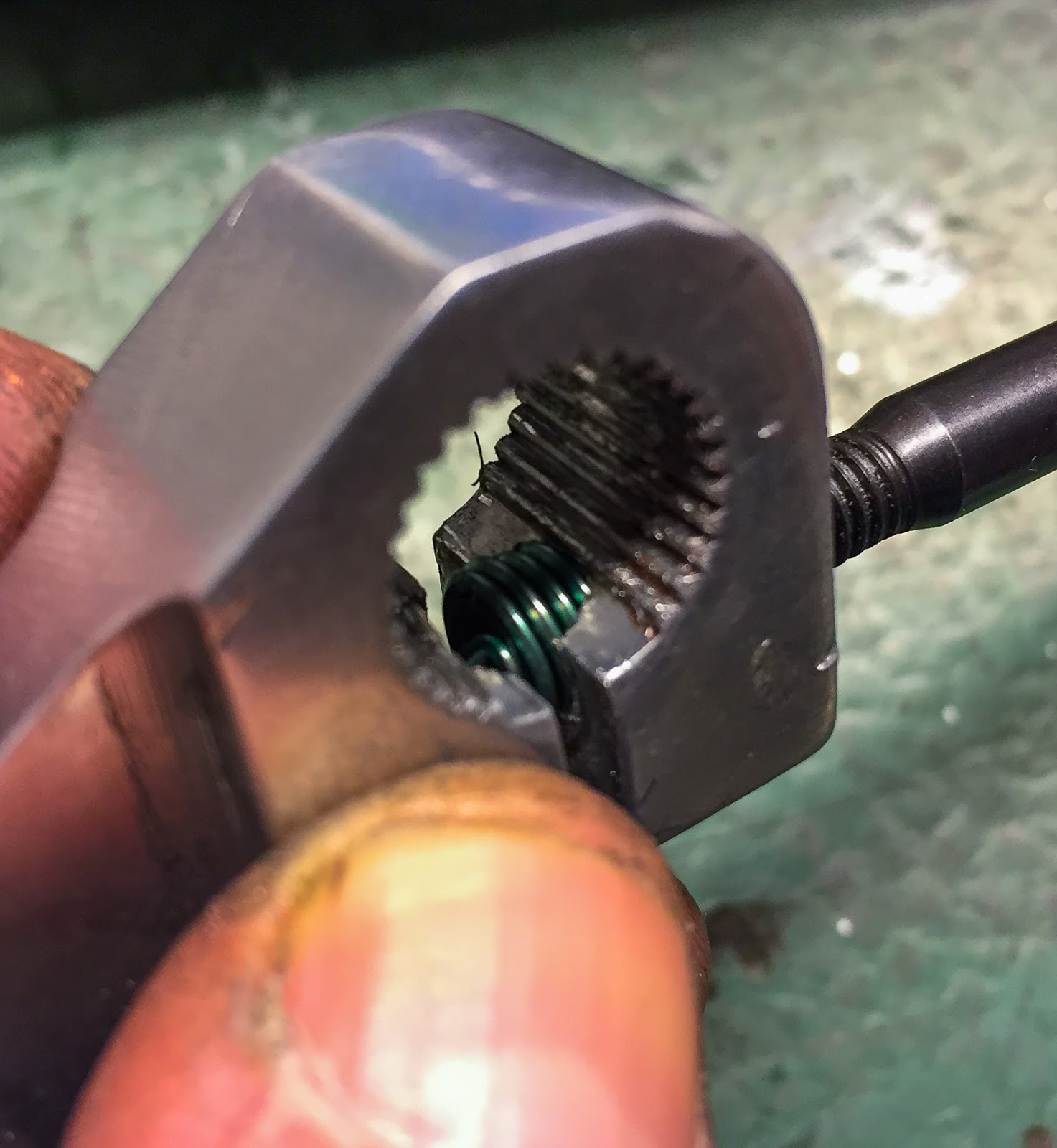
As I began checking and assembling the outer brake levers I observed an issue… All of them have metal thread inserts to bolster the threads inside. I consider these is perhaps manufacturing facility mounted. all 5 levers, entrance and rear have them. The issue was certainly one of them had damaged and partially adopted the screw out once I disassembled the components. On the left right here you’ll be able to see the metal thread outdoors the lever. The simple repair would have been to decide on a bigger screw and simply thread the opening. No can do! This wanted consideration.
A few years in the past I purchased the commonest thread restore kits from Helicoil. Sure, I had the M6x1.0 in inventory. Thanks, my hoarding obsession!

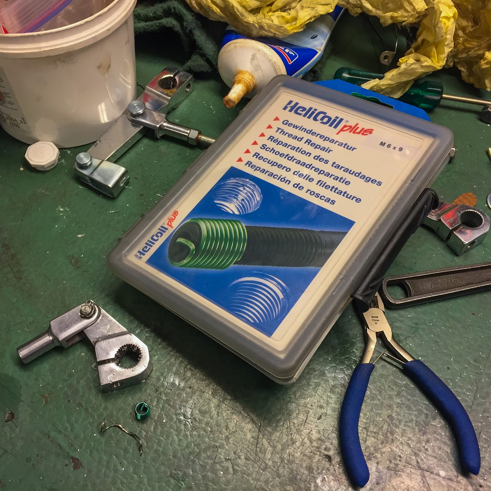
These are implausible kits with the whole lot you could make a everlasting thread restore included. This one has 9 mm size thread inserts, drill, faucet mounting instrument and the mandrel to complete the work. Multi function handy field.
Normally if you begin a thread restore you could drill out the opening a bit. The drill within the package is the right dimension for the threading instrument, faucet. Since there already had been inserts in these components I figured I might be OK simply to scrub the threads with the right faucet. Labored like a allure!
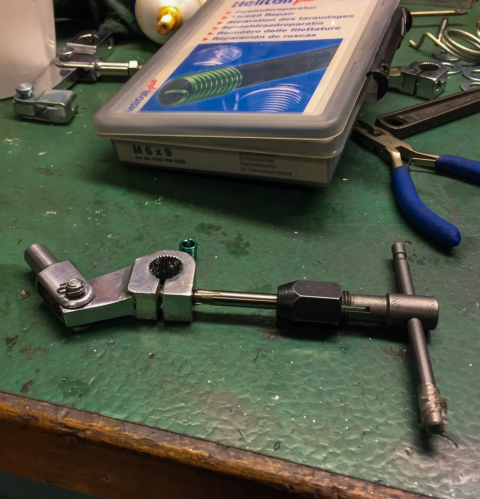
The subsequent step is mounting the brand new insert into the opening. Right here it’s on the mounting instrument able to be “screwed” in to the thread. The concept is straightforward: change the damaged aluminium threads with a extra sustainable one made from metal.
That´s why you need to make the opening bigger after which smaller once more inserting the brand new, a lot stronger, insert. Genious.
This a part of the method is delicate however not troublesome. the insert needed to be screwed by the primary a part of the lever into the second the place it’s purported to go. No huge deal, the mounting instrument holds it firmly so long as you flip it the proper method. Right here I´m midway by the primary layer.
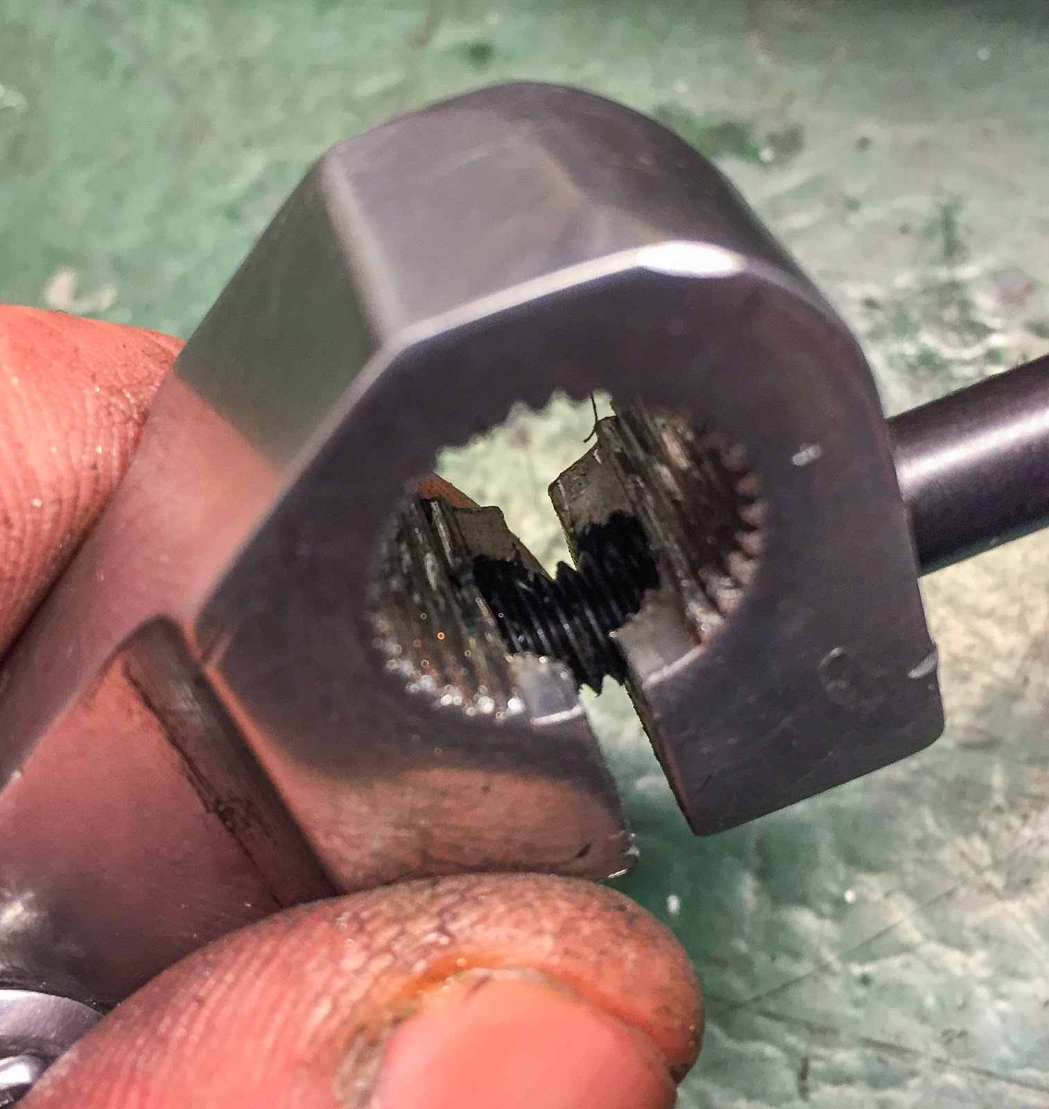
And right here I´m by and in to the second. It’s essential to get the tip of the insert at the least a few threads into the products for it to remain correctly. You can too use a drop of Thread locking glue, like Loctite, to safe it in place.
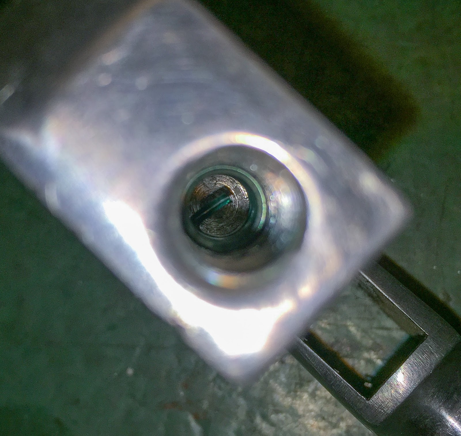
The final step of the method is eradicating the little “tab” used for the mounting instrument to drive it in to the thread. This tab will hinder the screw from going by if not eliminated. The mandrel is used to easily faucet it off.
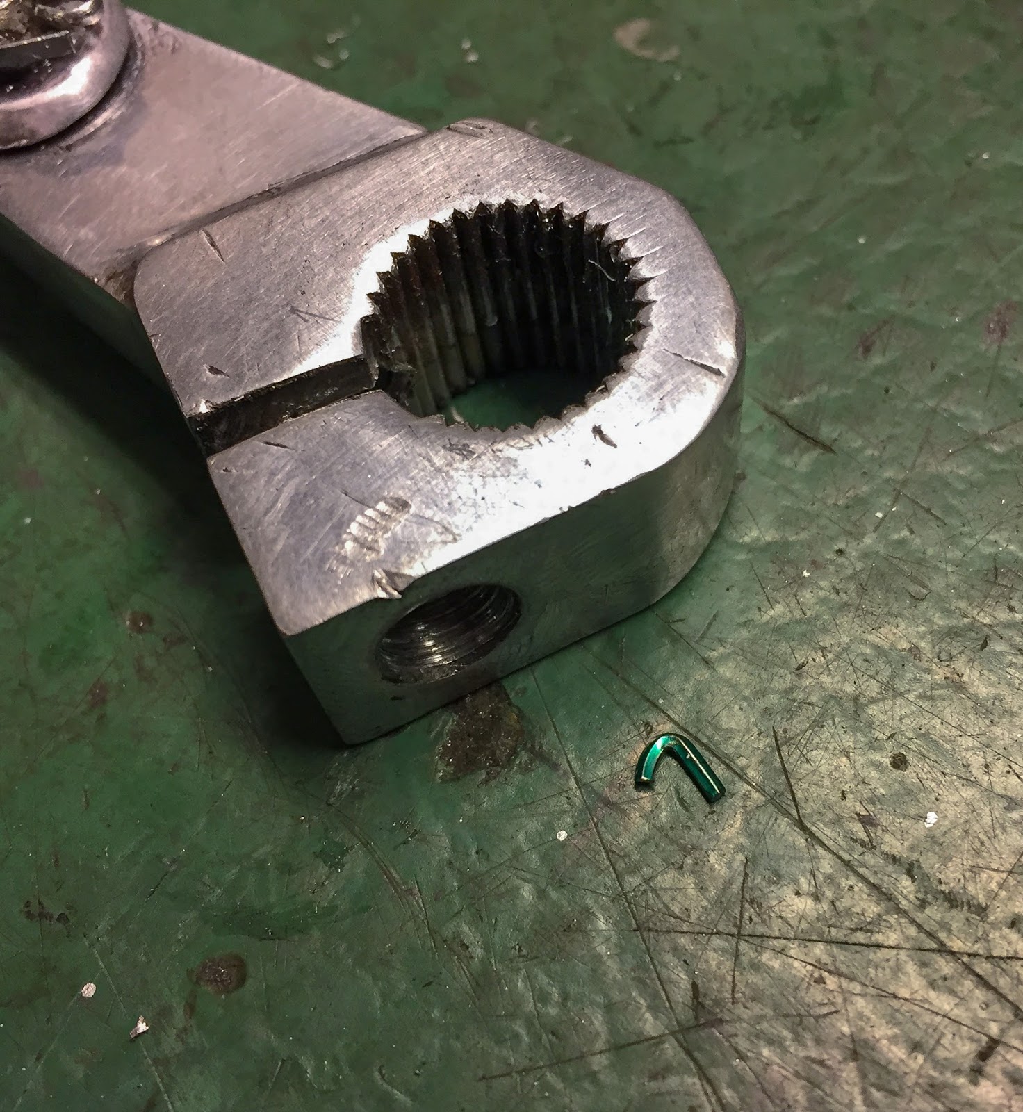
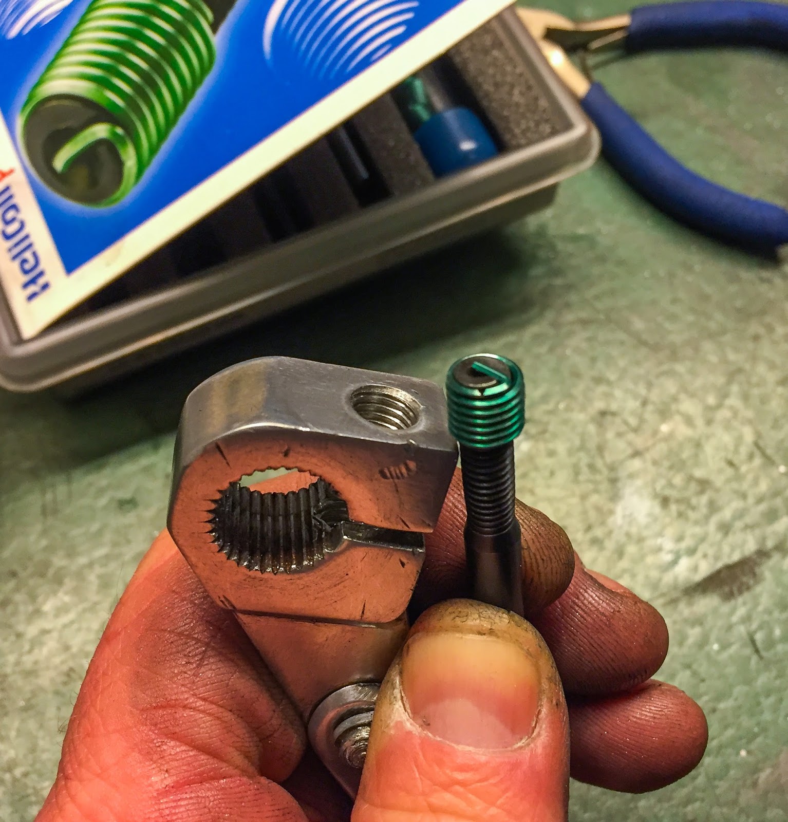
And right here is the affirmation the restore is full! the small finish faucet out of the opening. You don’t want this half round within the gap if you´re executed. Right here it’s not that necessary, however think about a restore on an inside engine thread….
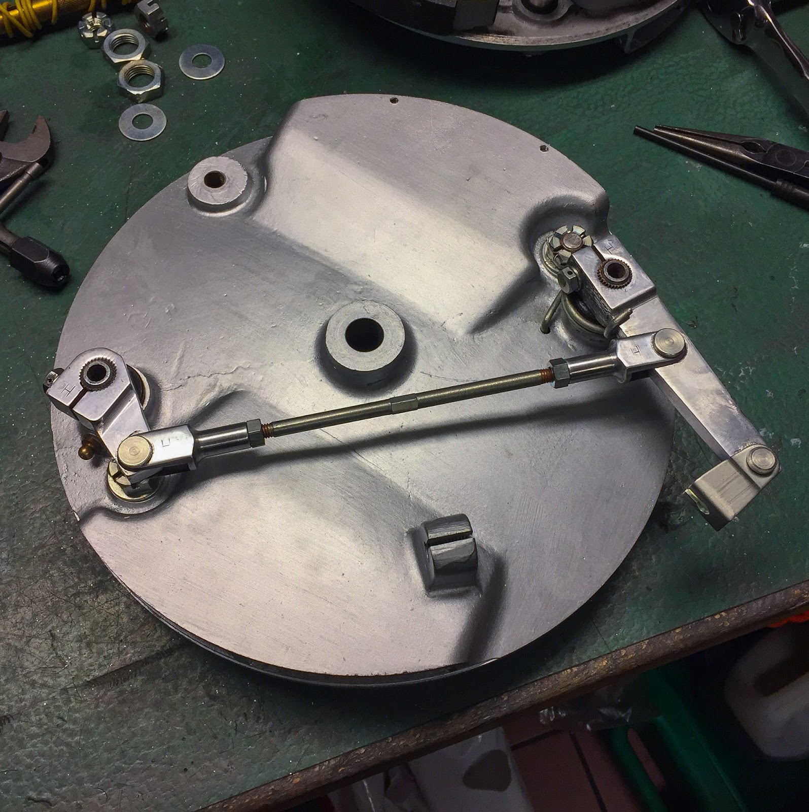
Time to get the levers and adjusting rod on to the brake plate. Cautious comparability with the photographs taken earlier acquired it proper in the long run (I feel….). If I goofed right here it´ll present when I attempt to modify the brakes and mount the cables to the levers. After which I´ll simply must take away the whole lot and do it over again. That isn´t in any respect unusual in my storage. Expertise tells my I do the whole lot at the least two occasions….
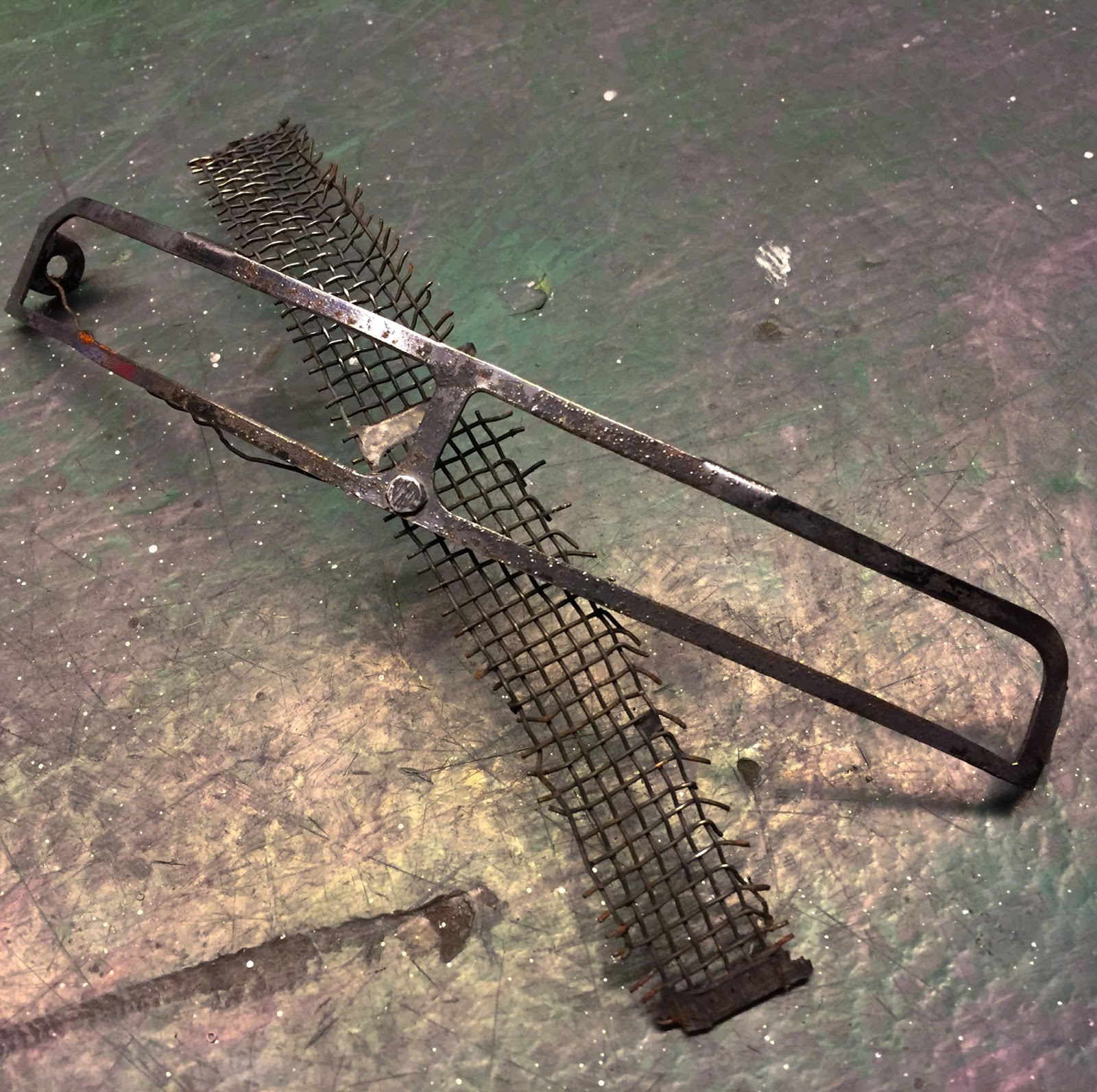
The ventilator plates on the entrance drum additionally wanted some TLC. This one is the worst of them. The online had separated from the body and it had additionally been bent and broken earlier. My plan to interchange them with new ones didn´t work out that nicely so I needed to repair them pretty much as good as attainable.
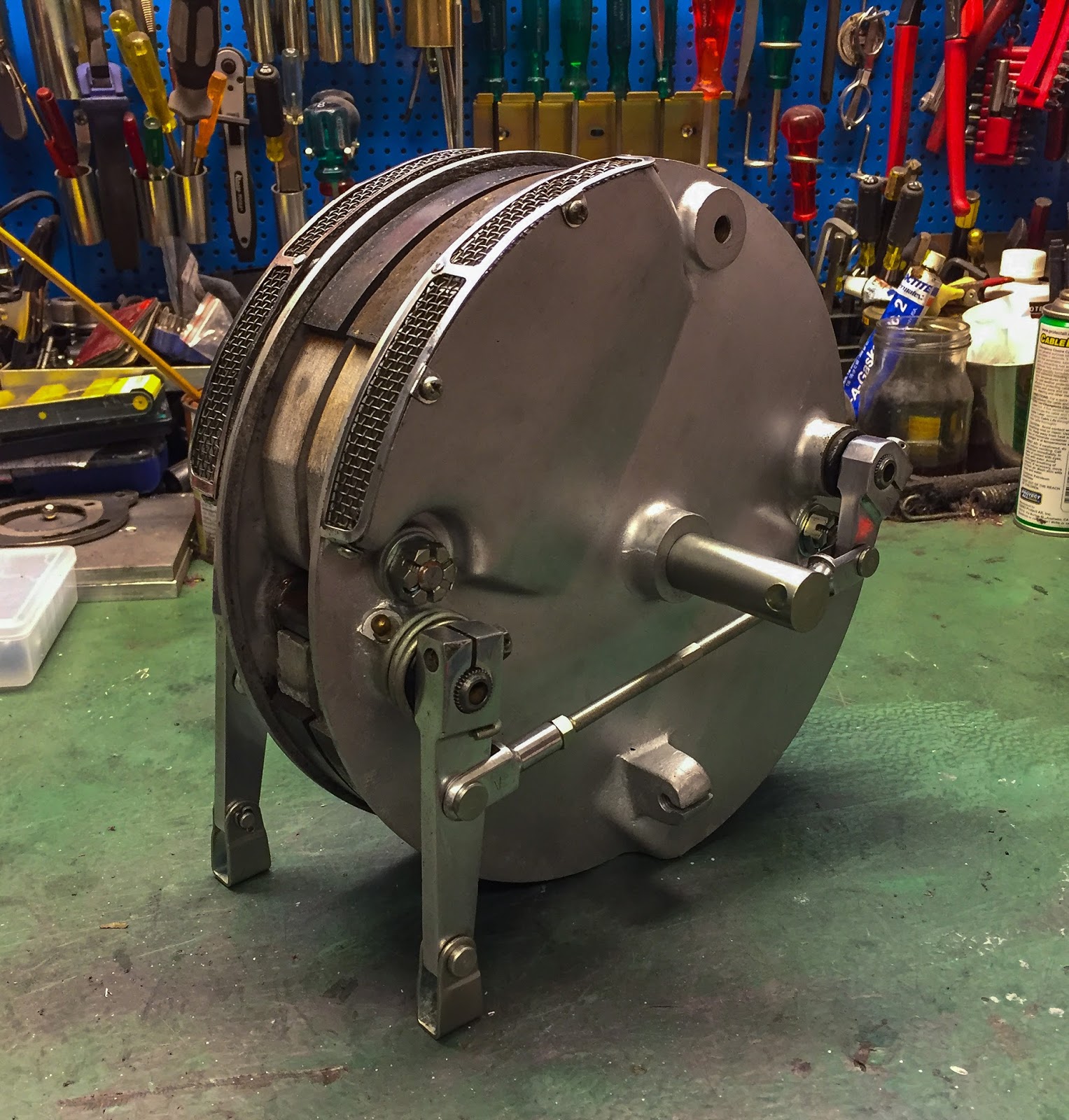
It took just a few ours throughout two days of great storage work to get it executed! Right here it’s, able to be inserted in to the entrance wheel. The brake shoe pivots have been secured with cotter pins however I´ll wait till the whole lot is completed and adjusted on the bike earlier than security wiring the screws on the levers. I don’t wish to try this twice as nicely…
The entrance brake completed. You possibly can see the restored ventilators and likewise the surprisingly good brake sneakers. They present nearly no put on in any respect. I consider Björn acquired a few new units when he purchased the bike from Flöter. I´m fortunate, as a result of discovering these sneakers are troublesome. There´s at all times a chance to revive outdated ones and have new brake linings glued on to outdated sneakers. I´m blissful to not have
to cope with that as nicely!
Entrance view of the entrance brake. I´m very proud of the turnout of this half! When you will have the drum free like this it’s also attainable to determine methods to modify the levers afterward. I do know from a earlier restoration of a Suzuki GT750 J 1972 that these 4LS brakes truly are fairly environment friendly when adjusted appropriately. It’s essential to be thorough and meticulous doing it, although. nicely, that journey awaits sooner or later.
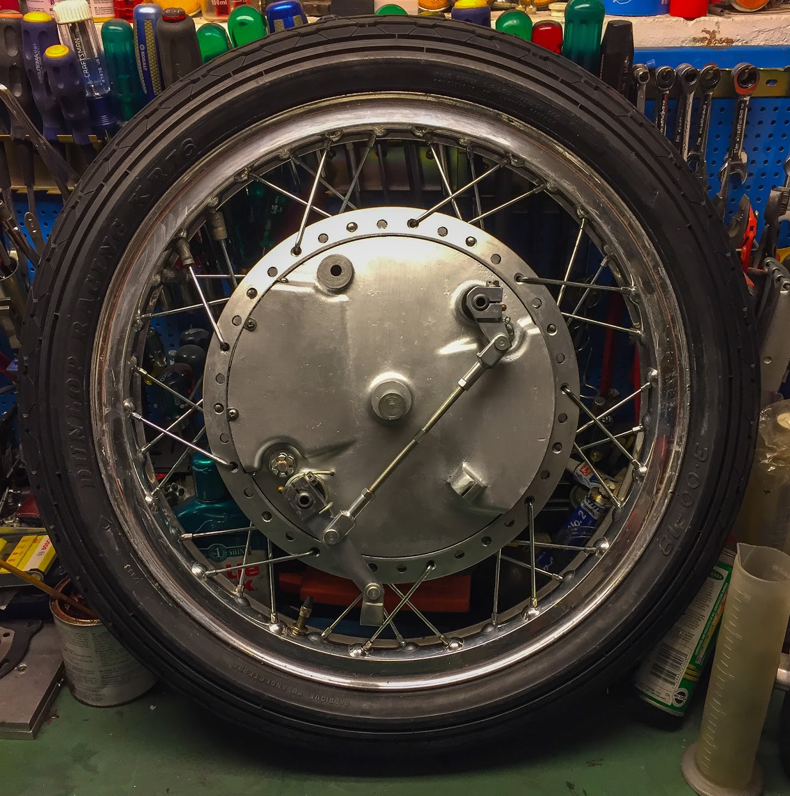
For now it was very rewarding to place the brake plates in to the wheel and snap a few pics. I´ve stated it earlier than… These are murals!
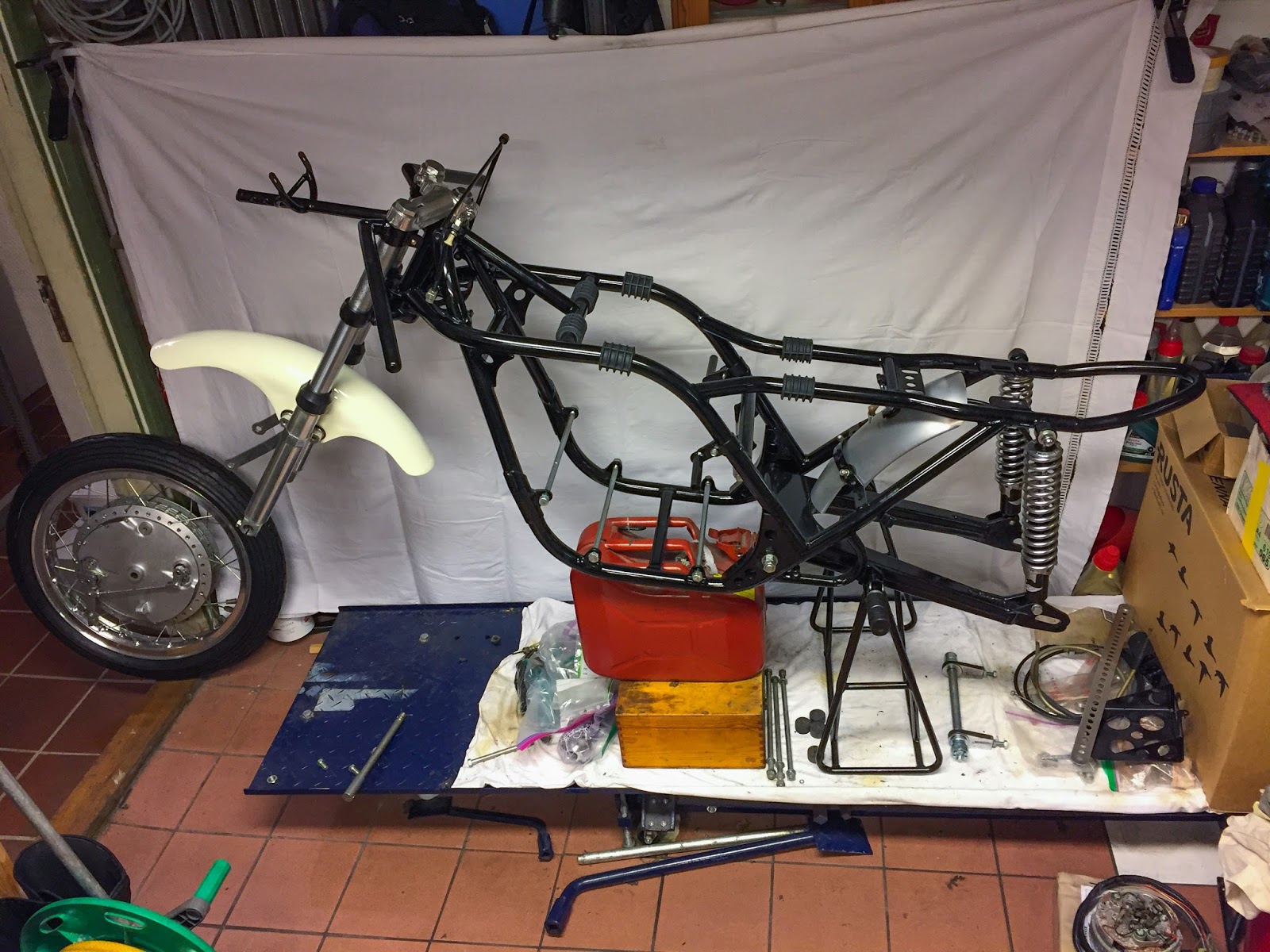
The entrance and rear wheel able to go on to the body. Now I have to get going with the remainder of the chassis. I would like the primary stand to mount the wheels and to get the primary stand on I would like the entrance foot pegs in place. To get them in place means I’ve to repair them first! Right here we go!
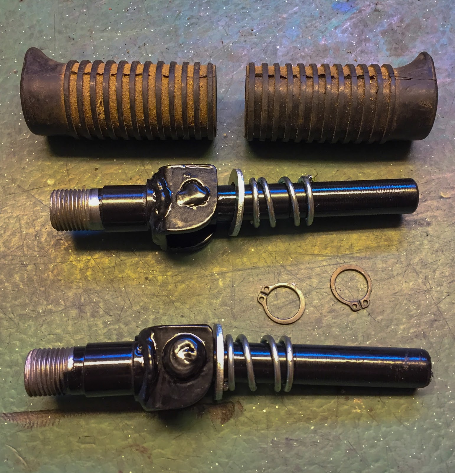
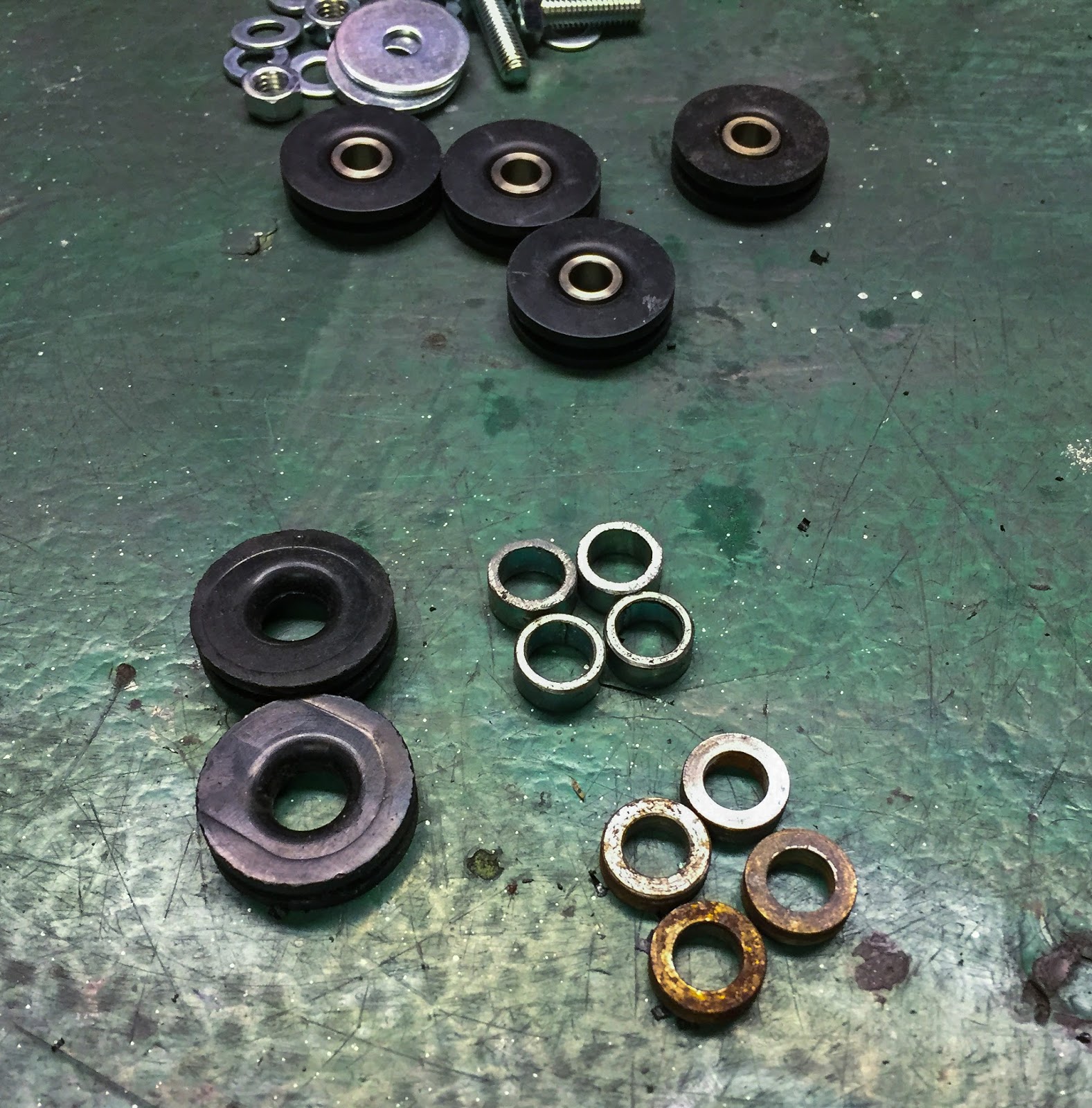
The pegs had been painted along with the body and swing and so forth. All the opposite components had been rezinked and saved in baggage. On this image we are able to see the outdated foot peg rubbers and the refurbished pegs, springs and washers. I needed to discover new locking rings, although. Gone with the wind! The one issues lacking listed below are the second washers on every peg. They go between the spring and the locking rings. A plan arose when taking a look at these components… I used to be questioning if I may reuse the outdated foot peg rubbers as a substitute of placing on new ones… You already know, I wish to reuse as a lot as attainable right here. The one drawback was certainly one of them was cracked partly and that wouldn´t look too good. I got here up with an answer!
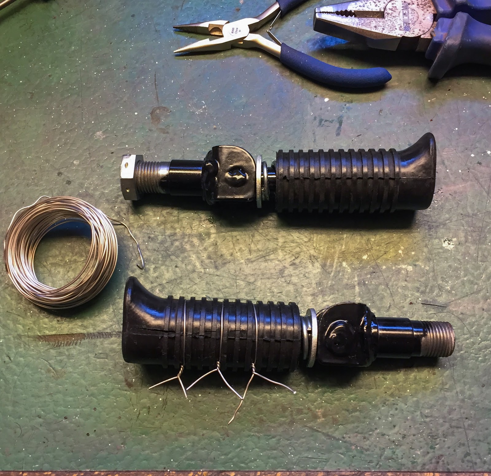
In fairly just a few footage from the racing tracks throughout the day I´ve seen these rubbers being tied with wiring. I consider this was executed to maintain them in place throughout racing. What if I may replicate that wiring and maintain the cracks collectively on the similar time? I purchased a security wiring package together with some high-quality stainless wire. I put three of them in place tying the rubber up sufficient to maintain the crack from “cracking” when not on the foot peg. As I slid the rubber on to the peg the crack stayed closed and the rubber was held significantly better and firmer in place. NICE!
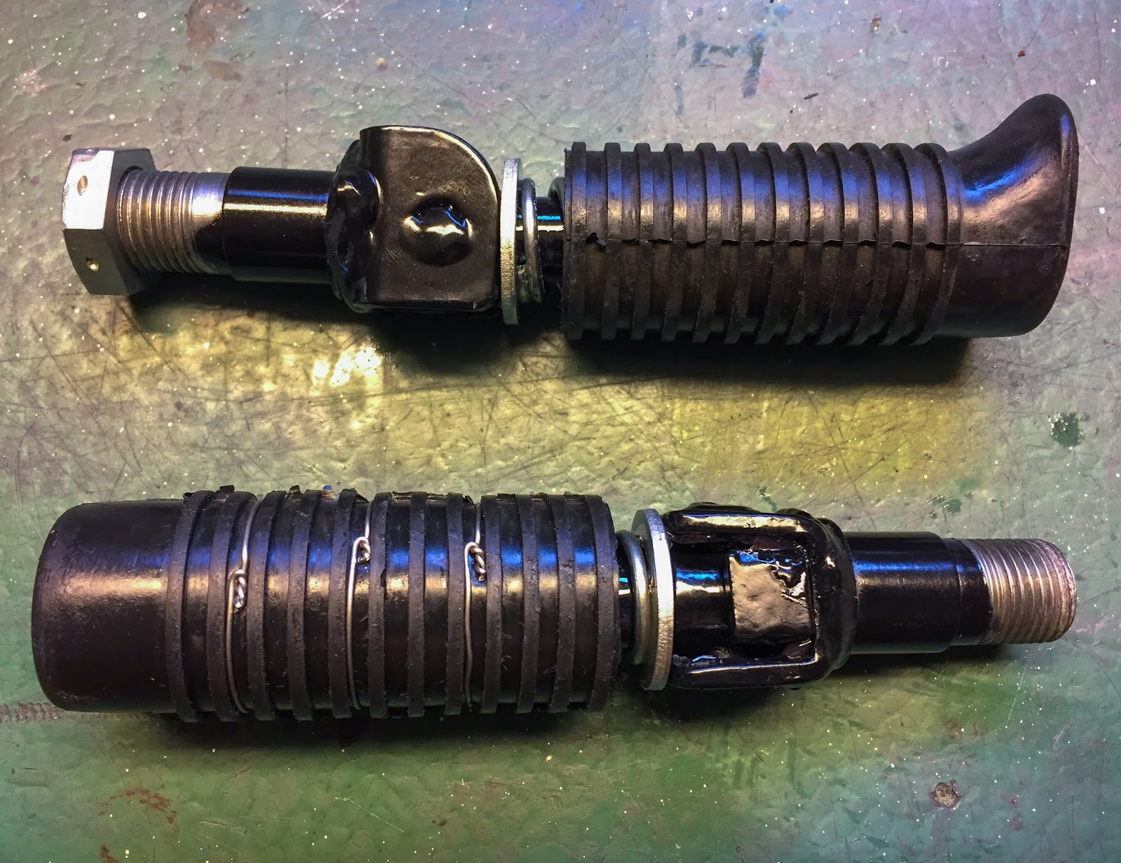
The excess wire was minimize and the joints had been positioned on the backside of the rubbers and gently folded contained in the rubbers. This can look very real when on the bike. I feel I´ll do the opposite rubber the identical method, despite the fact that it isn´t wanted.
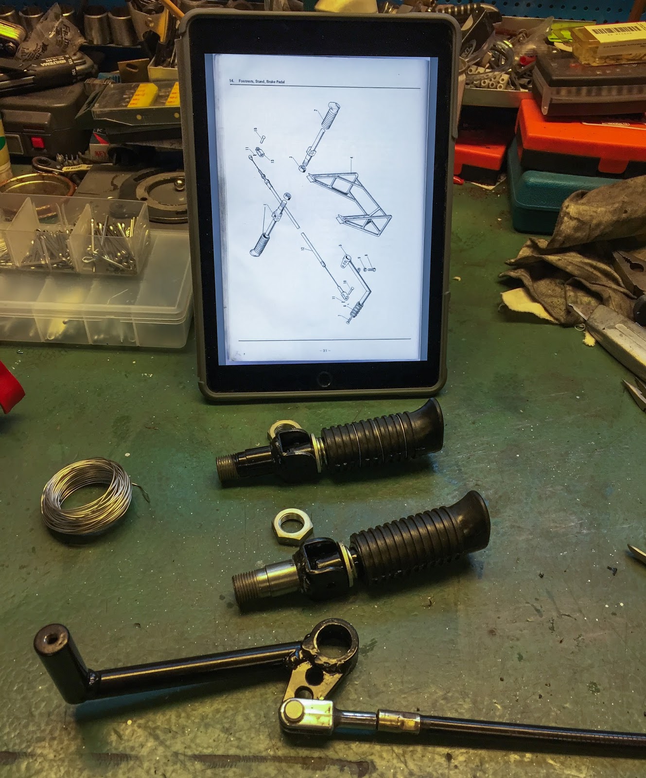
The rear brake cable and brake pedal was subsequent. It mounts to the foot peg and has to go on the body on the similar time. A bit of grinding on the peg to get the pedal on. The cable needed to be cleaned and greased. Fortunately it’s in excellent working situation with all components intact and in good nick. Having the spare components ebook helpful when assembling stuff could be very neat. I´m a contemporary man so the iPad does it!

Right here it’s on the bike. I had it on and off about 3 times earlier than realizing I had all of it incorrect anyway… The brake resting level adjusting screw shall be inserted the opposite method round first with the locking nut on high of the body bracket earlier than placing the foot peg on. I´ll repair this later… Subsequent up was the entrance fender mounting!
Ihave been pondering this again and again many occasions and at last got here to the conclusion I might use the H2 aspect cowl grommets along with collars a bit slimmer than the unique H1R components seen under, proper within the image. I needed to scale back the peak of the thinner collars to suit correctly on the fender contained in the grommets.
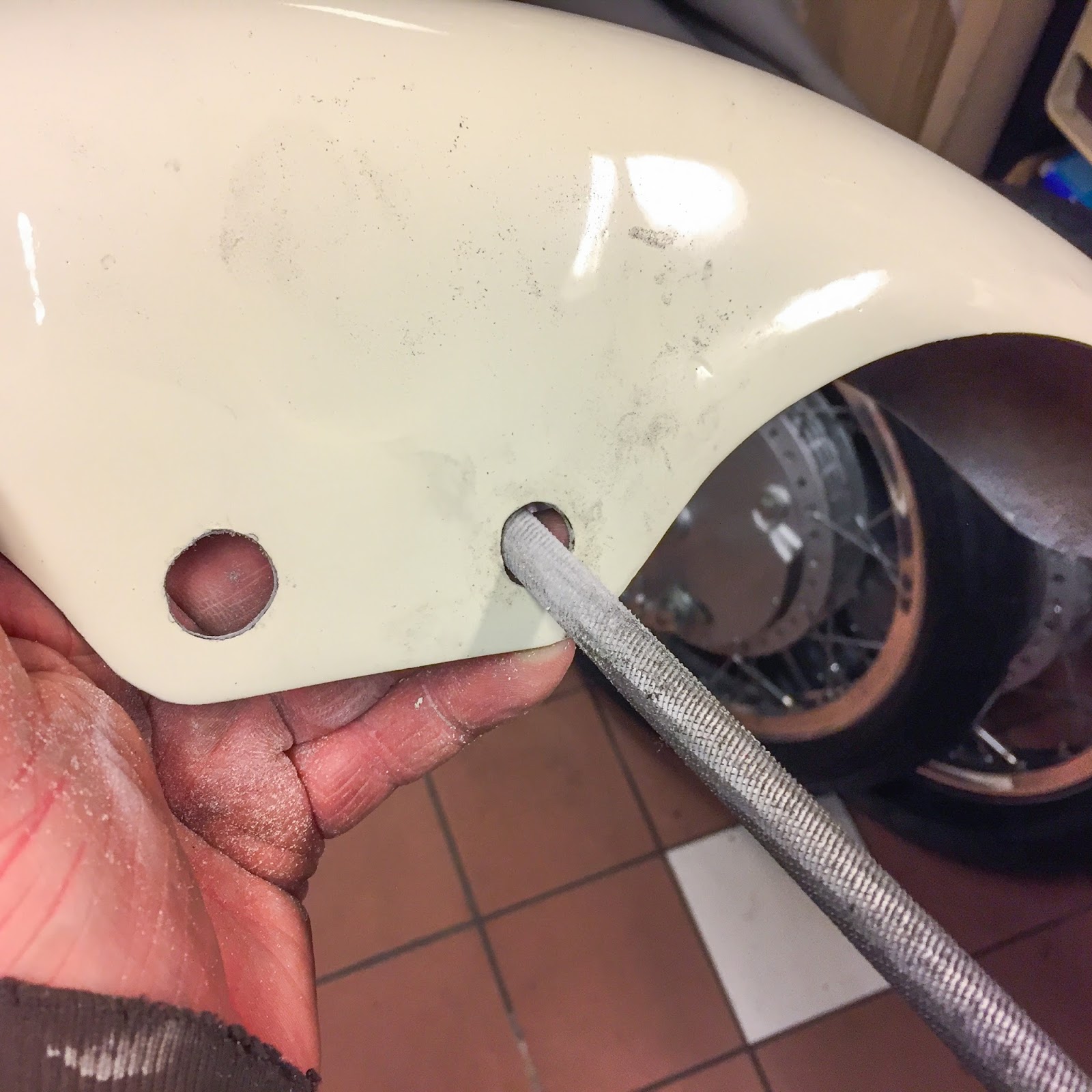
To suit the grommets within the fender holes I needed to enlarge them a bit. Shaky enterprise taking a rough file and submitting away on these components!
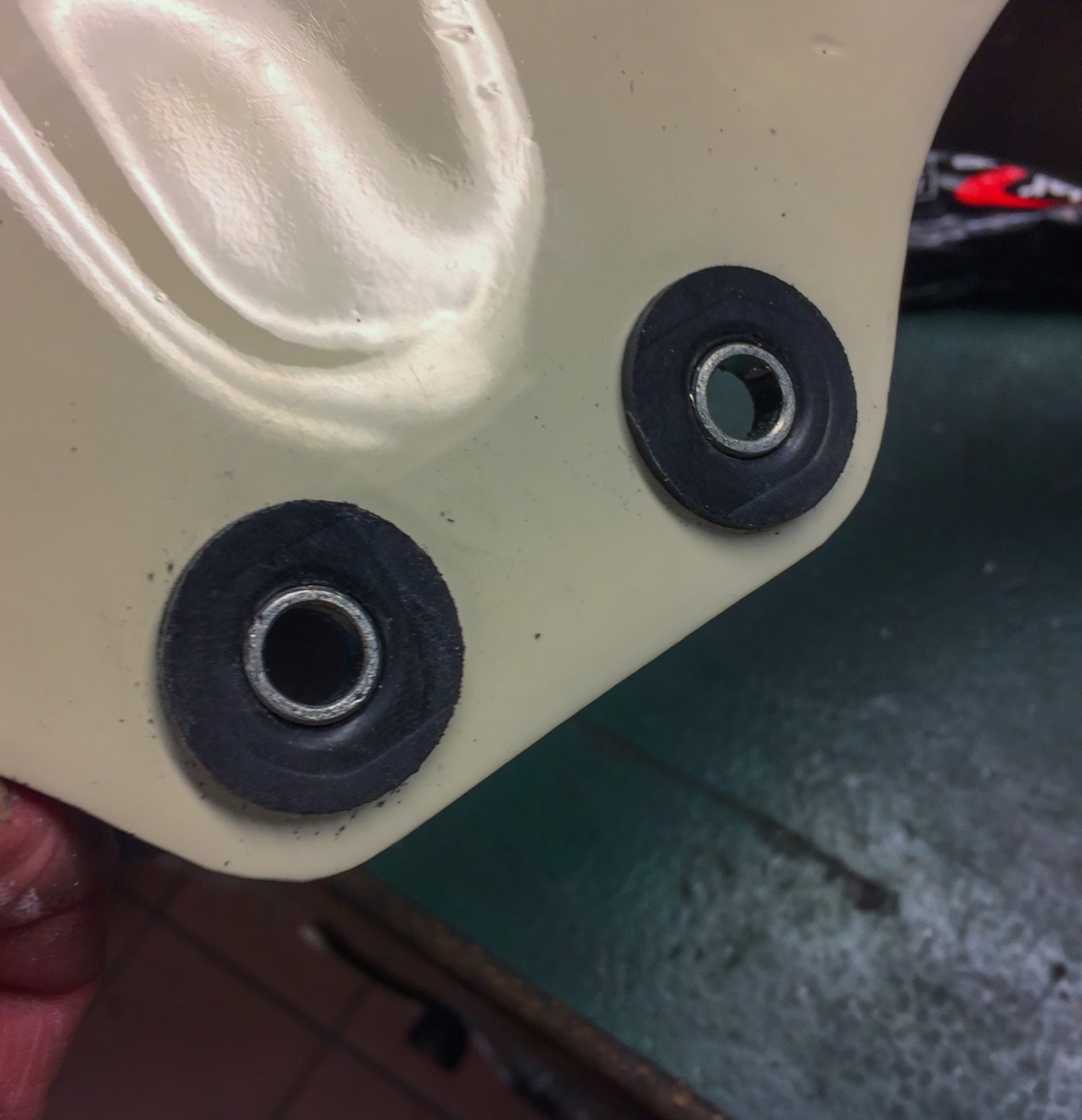
This manner the fender might be rubber mounted for actual! I do know this might be non-original, however I feel it’s an enchancment in comparison with the inventory mounting. It won’t be seen in any respect however will hopefully maintain the fender from cracking.
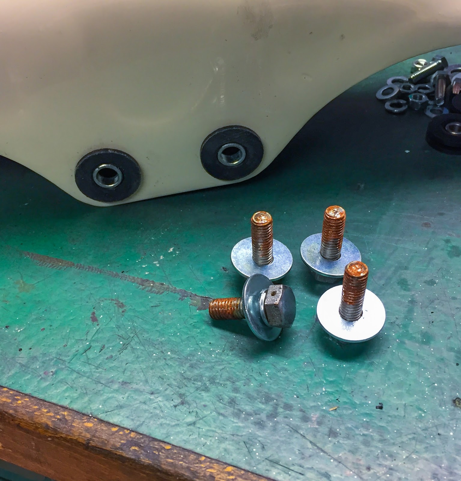
Since I selected the slimmer collars I didn´t must enlarge the holes greater than obligatory and will nonetheless use the unique mounting screws. Right here they’re, greased and able to be put in with the fender within the background.
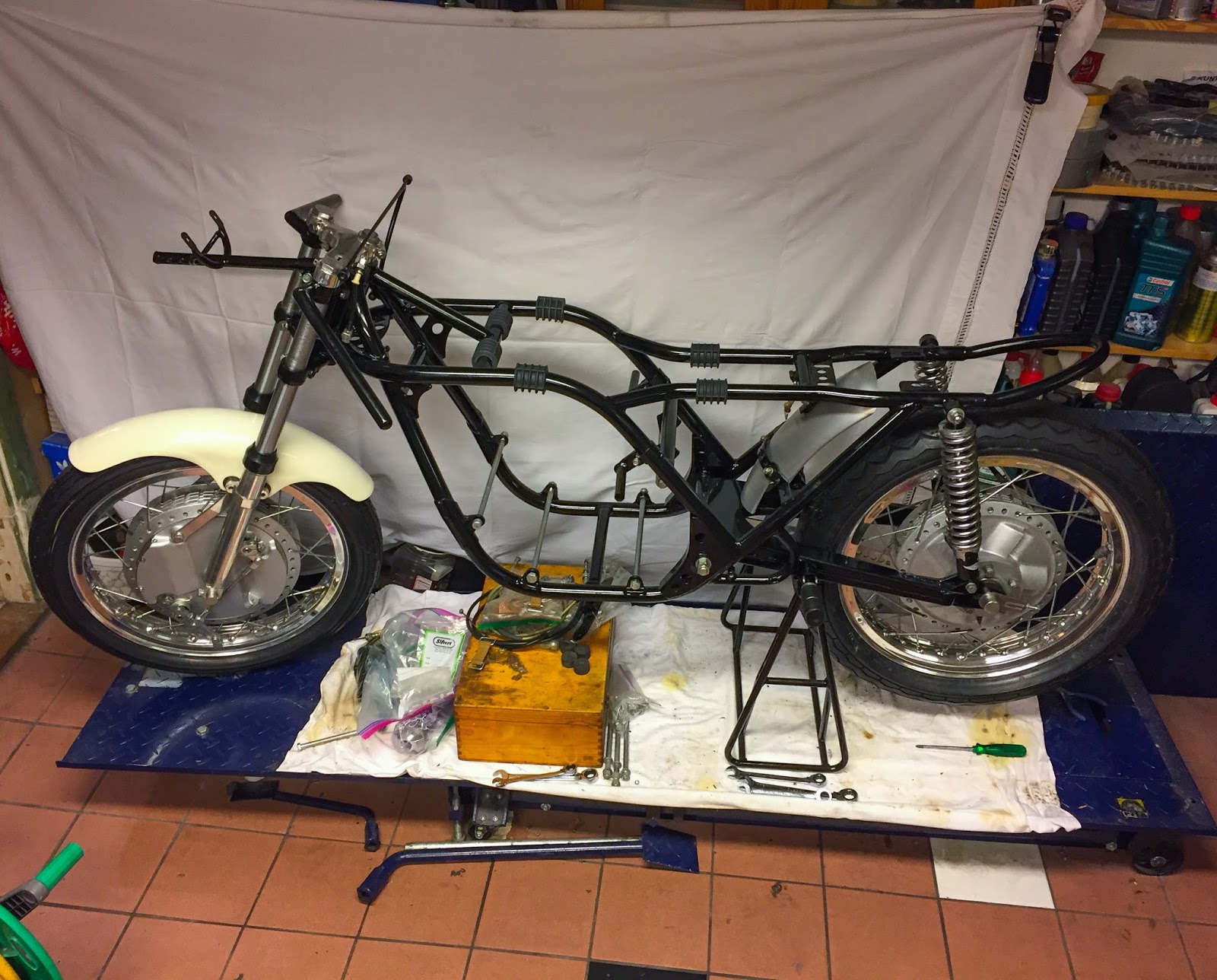
OK, time to get the wheels on the body. First the body needed to go up on the primary stand. Right here it’s, beneath the motive force foot pegs. On reflection I ought to have began with the rear wheel from a balancing standpoint. However why make it simple?
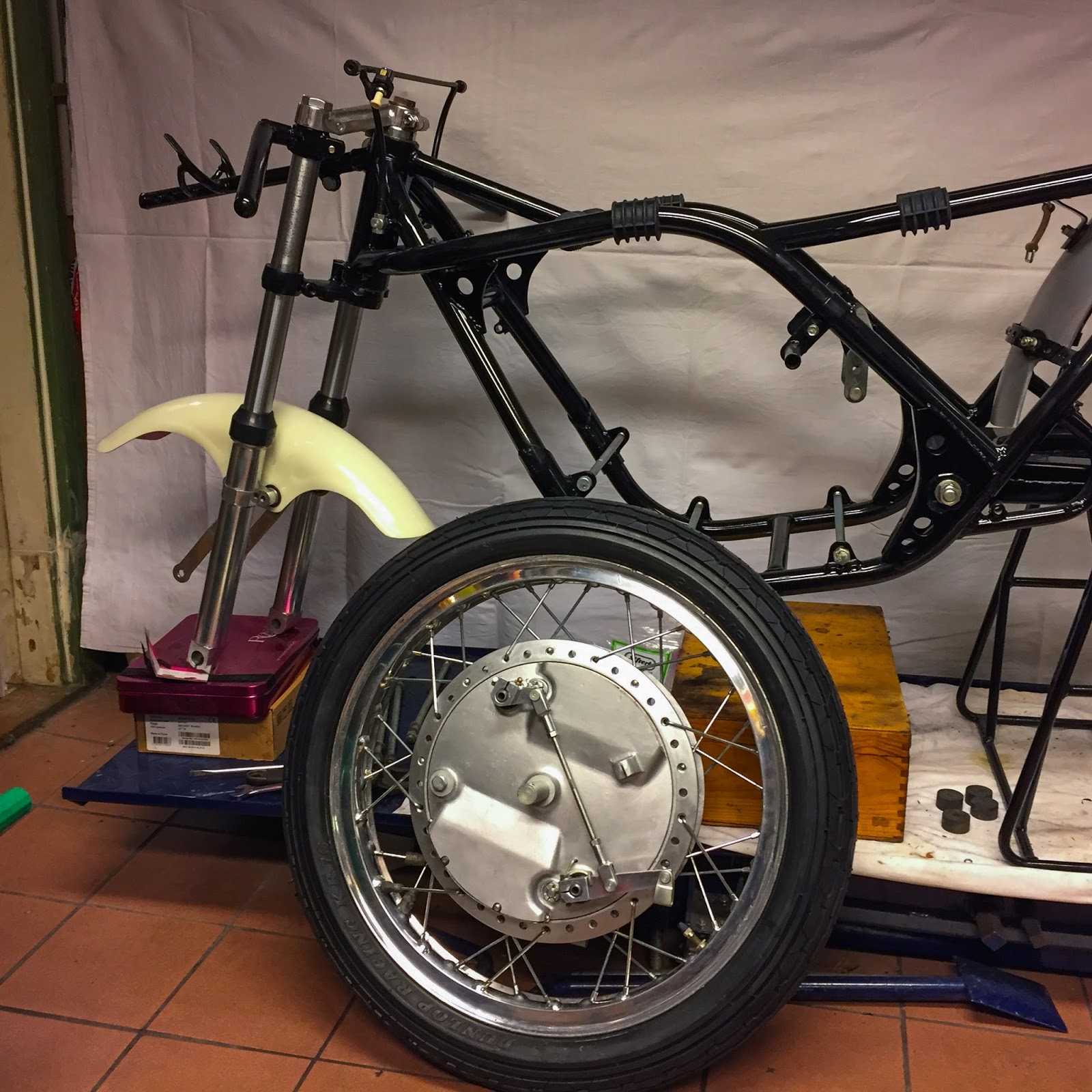
I needed to stability the bike on the primary stand and containers and so forth to get the entrance fork excessive sufficient to get the wheel in there.
It took a few tries to get the peak proper. The combo of the spare components wood field and an empty gasoline can acquired it excellent! Bear in mind I at all times do issues at the least two occasions? First I attempted placing the wheel on with the tire pressurized. Didn´t work. The tire is simply too extensive to get by the area between the fender mounting screws… Second time I acquired the wheel depressurized first. It handed the screws and the axle slid properly by the entrance fork decrease tubes and wheel solely to search out I had mounted the entrance wheel brake torque brackets the incorrect method. Off with the whole lot and the third time I lastly acquired it proper. You study as you go alongside!
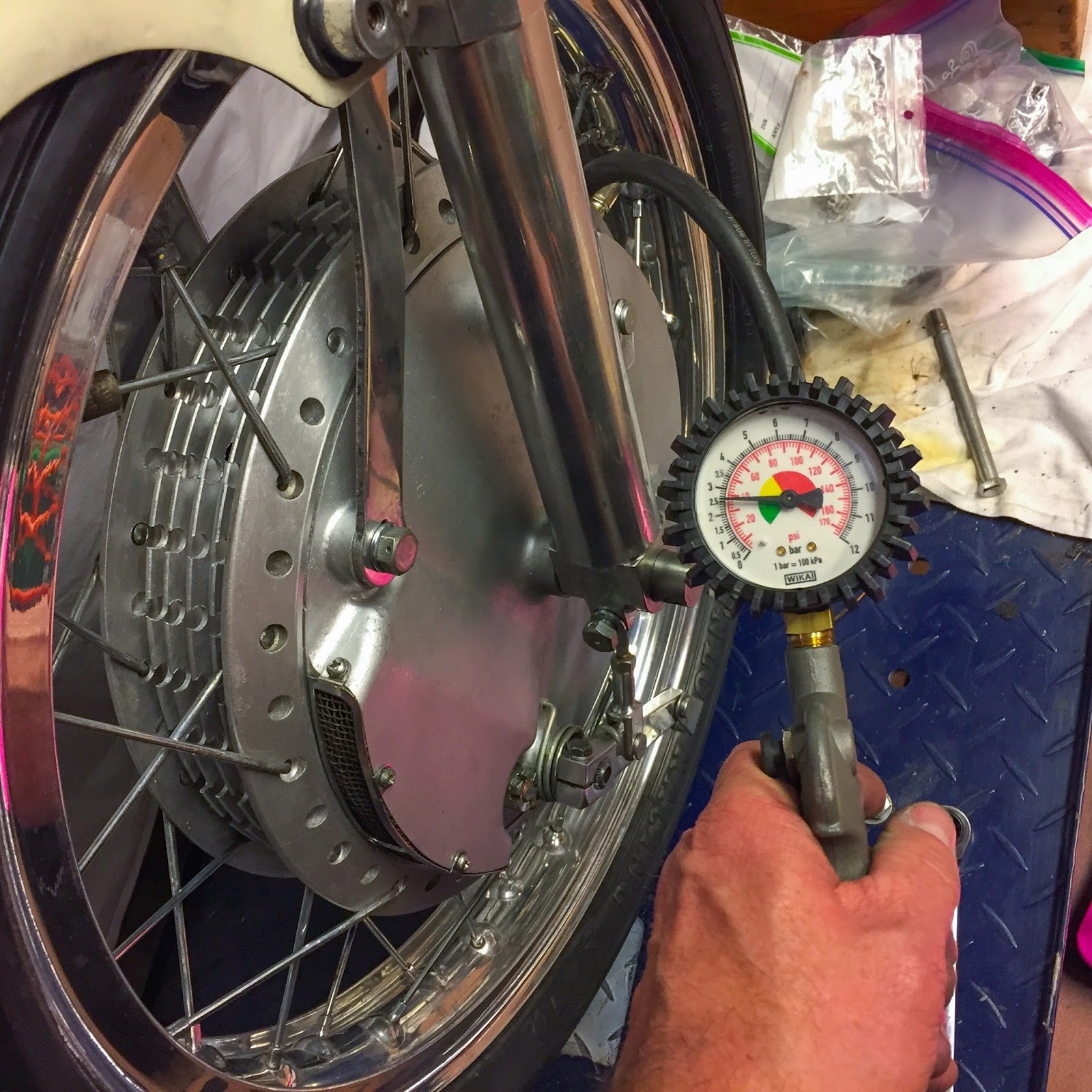
It was with nice pleasure I may re pressurize the entrance tire and at last fasten all of the {hardware}. For now, anyway…
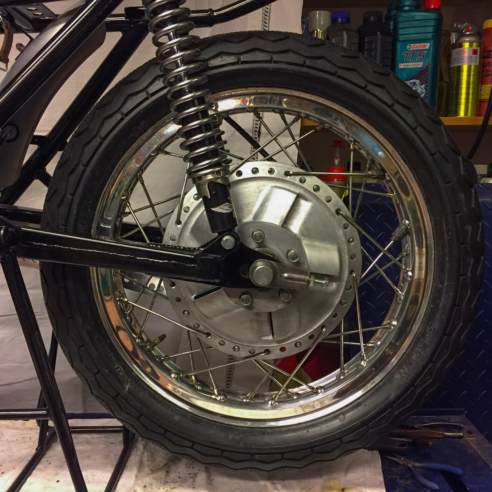
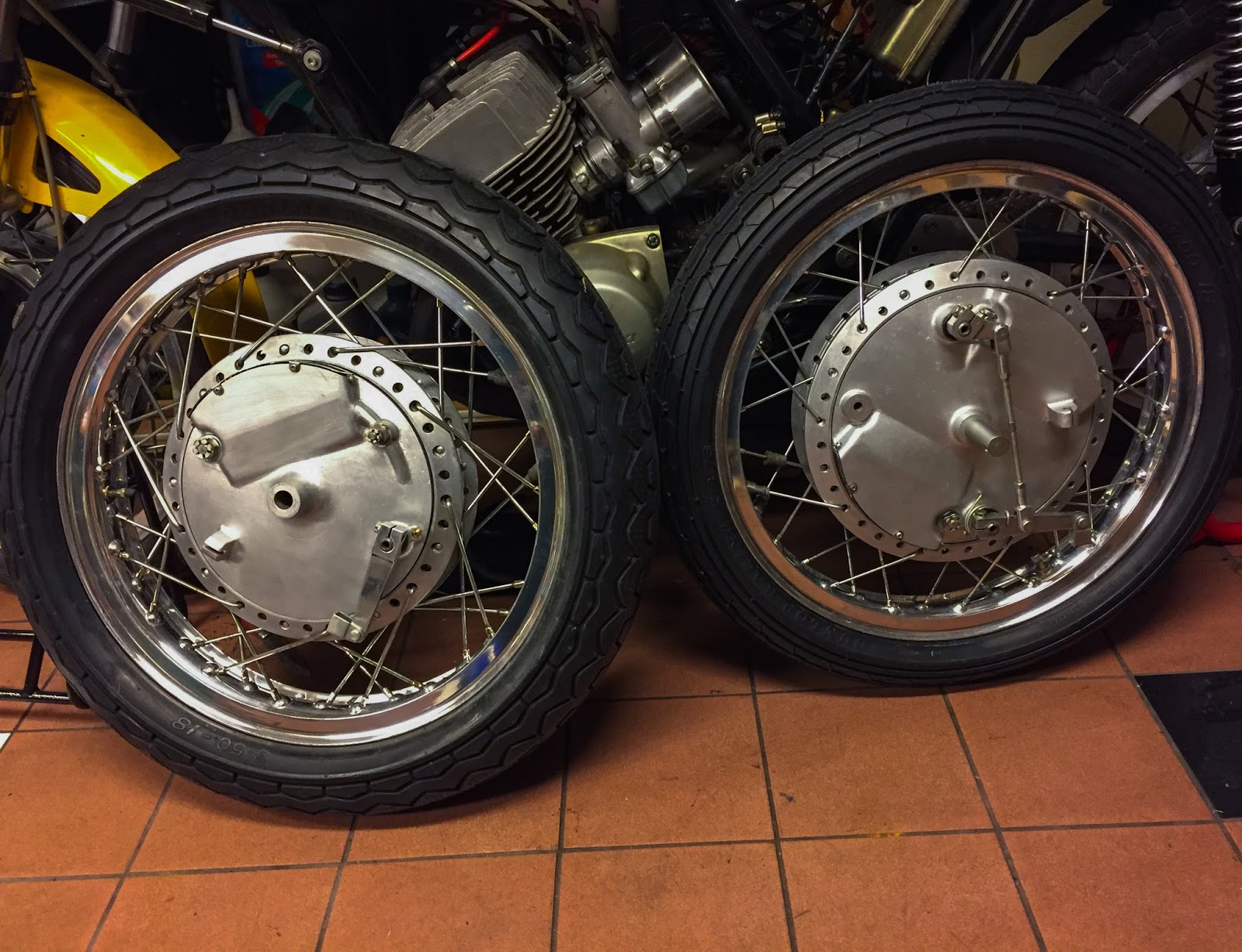
The rear wheel is quite a bit simpler. Just one brake plate to carry throughout meeting. The rear took solely a 3rd of the time to get in place in comparison with the entrance one. Bear in mind the sorting drawback I discussed earlier? Properly, that grew to become apparent once I tried to put in the rear brake cable within the rear brake lever cable bracket… There are 3 lever cable brackets on the bike, two up entrance and one on the rear. The rear one has a bigger opening for the rear brake cable lug. That is bigger than the 2 up entrance. Guess the place I had put the rear one? Yeah, up entrance, in fact. To my protection, they aren’t that very totally different. That price me one other hour of small, irritating fettling in cramped areas behind the levers and the wheel spokes.

The ultimate result’s fairly good, although! Right here´s the entrance wheel in all its glory. Mounted to the entrance fork and prepared for brake cables and last changes. Possibly a little bit too shiny for my style however it´ll do for now. Getting stuff duller shouldn’t be that tough!
Lastly…. Right here it’s. On its wheels for the primary time since January this 12 months. I additionally acquired the higher fairing bracket on together with the refurbished “ignition lock”. As you’ll be able to see I needed to mount it upside-down. It wouldn´t match in any respect the opposite method. That swap may not be the right one or the bracket on the fairing bracket might need been modified by somebody earlier. I actually don´t know and albeit don´t care an excessive amount of about it both. I sort of like these small peculiarities that comes from a protracted historical past. We´ll see how that´ll play out afterward within the course of.
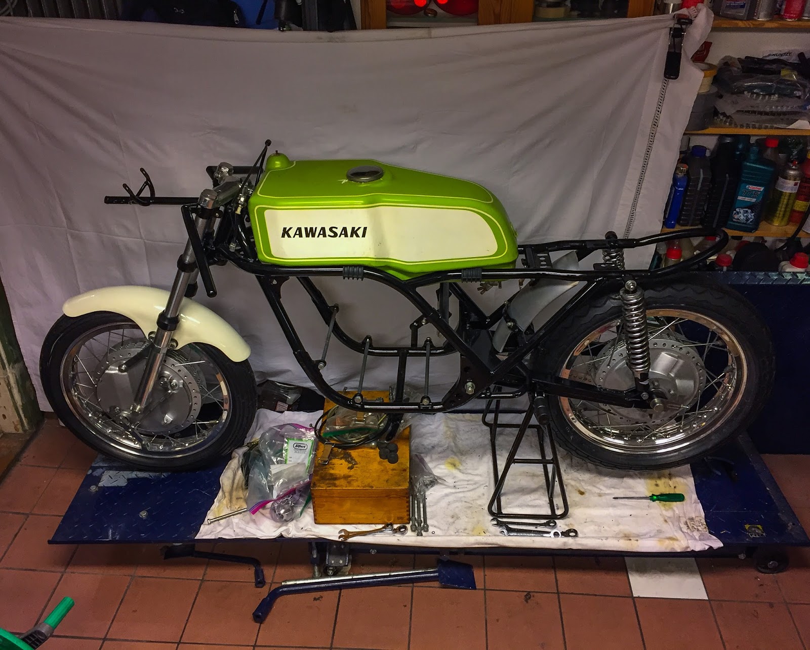
It was very tempting to place the tank in place… Appears nice, doesn´t it? If I had the seat it will look even higher however that should await some time.
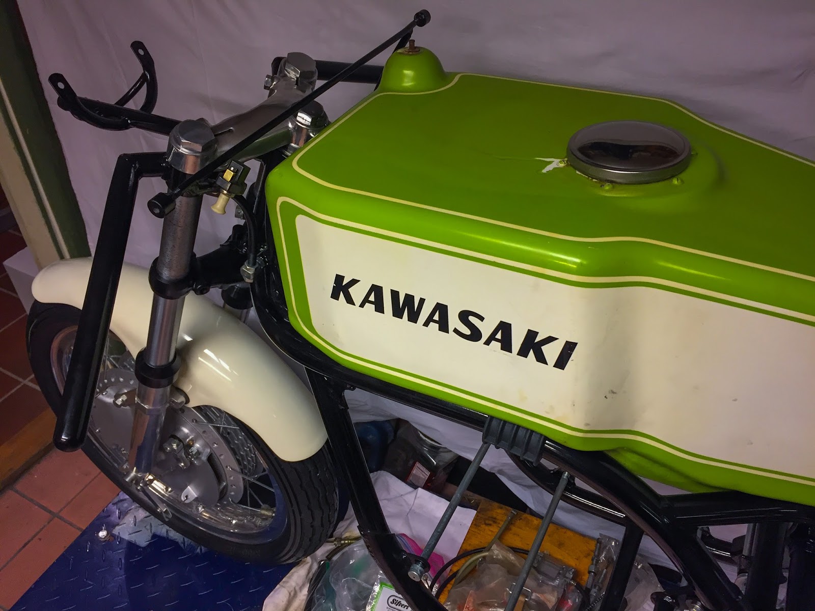
Right here´s a better have a look at the tank and high fairing bracket. That bracket could be very adjustable in its fastening to the body. I can solely hope this peak is right. If not, I´ll simply have to alter it. No biggie.
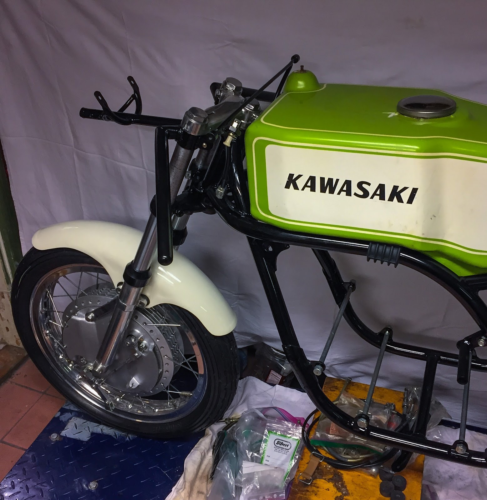
It’s actually starting to seem like a racer once more. That entrance finish is so stunning I can spend minutes simply taking a look at it. Right here I additionally tried out the engine mounting bolts. I saved a set from a really good H1-69 I parted out earlier this 12 months, however they had been too quick!
These are on no account the unique ones, and albeit they seem like sh*t. Handmade and never very properly manufactured in any respect. I´m going to verify if the H2 ones are a bit longer and should match higher. I do know I’ve some in inventory, someplace. Looking for components is one thing I do quite a bit!
The subsequent step could possibly be placing the engine within the body. Or I´ll proceed engaged on the chassis some extra. The RPM indicator, the deal with bar levers and cables all have to get on there. We´ll see. For now I´m very blissful to see it with the wheels on!
Keep tuned for extra…
/Per
[ad_2]