
[ad_1]
I´m nonetheless changing the unique ignition coils, 21121-037 with related ones from the H1B 1972, 21121-054 and 21121-055, since I’ve not been capable of finding the unique H1R coils….
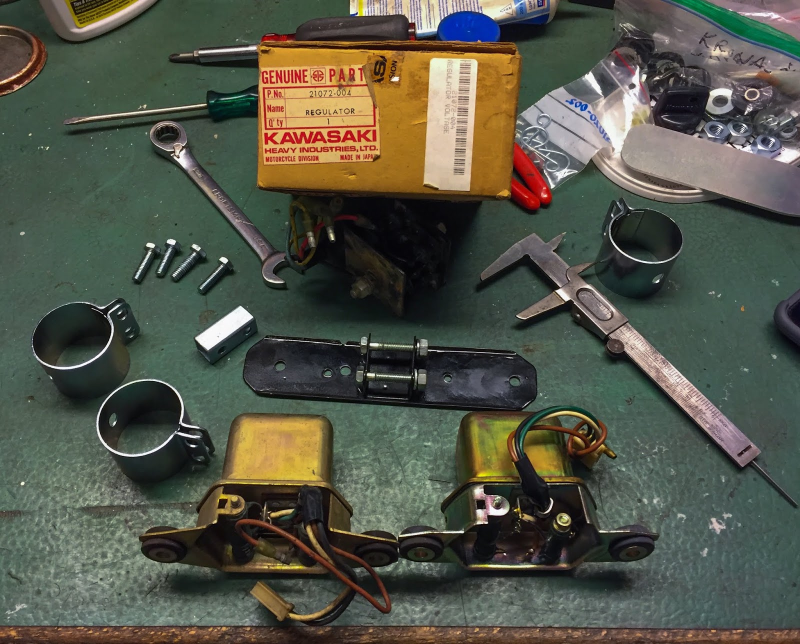
Now it was time to attempt to find all components wanted. I had two regulators, one NOS and one very good used. I selected the NOS one. Higher secure than sorry in the case of electrical components. Every little thing else within the image to the left will likely be mounted on the “spear” up entrance the place additionally the tachometer is mounted.
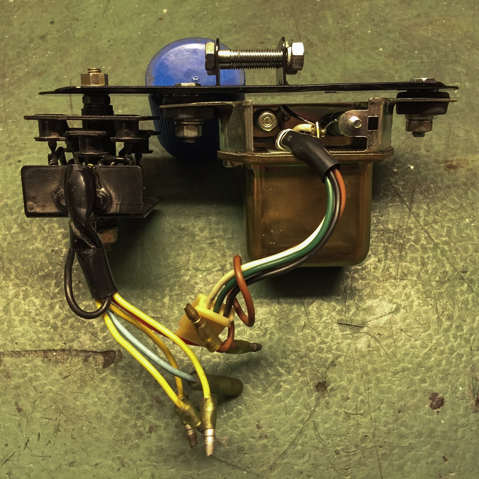
The regulator and the rectifier mounted on the bracket that goes on to the “spear”. Word how the regulator is rubber hinged, That is really authentic additionally on the H1R. The rectifier is simply screwed in place.
The used rectifier turned out simply tremendous after some cleansing. You may see the three diodes there, all in black, that turns alternating present in to direct present for {the electrical} system. The regulator retains the voltage inside limits to not overpower {the electrical} circuits. That one is a mechanical half that won’t perform correctly when uncovered to vibrations, therefore the rubber mounting. There´s all the time a motive….
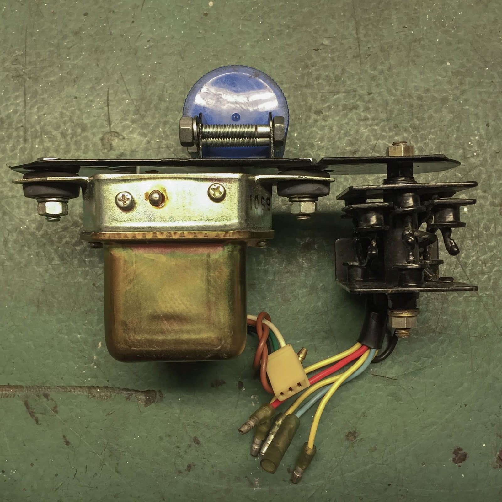
Subsequent was fixing the coils for mounting on the bike. The H1B makes use of a complete lot extra stuff across the coils to maintain them from vibrations and likewise climate. I don´t want any of it. They do have totally different half numbers within the catalogue however the precise coils are the identical. The size of wiring and the totally different brackets make out the variations.
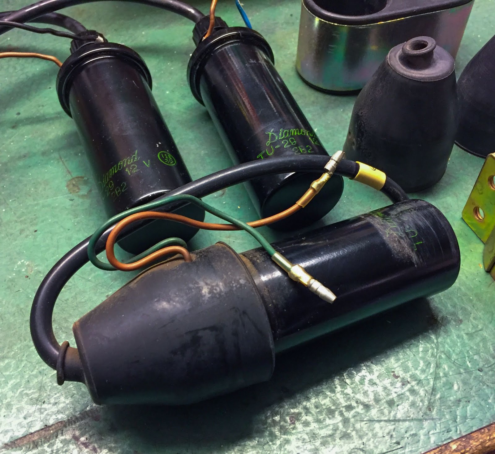
I´ll in all probability not use the wiring on the coils however they’ll stay, the big rubber boots should go, although. The identical goes for the clamps. There´s no room below the steering head for that enormous double clamp. And that´s not the way in which it’s purported to look.
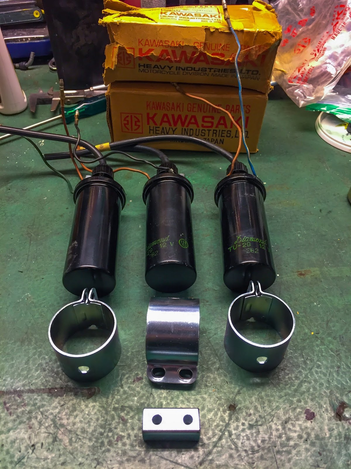
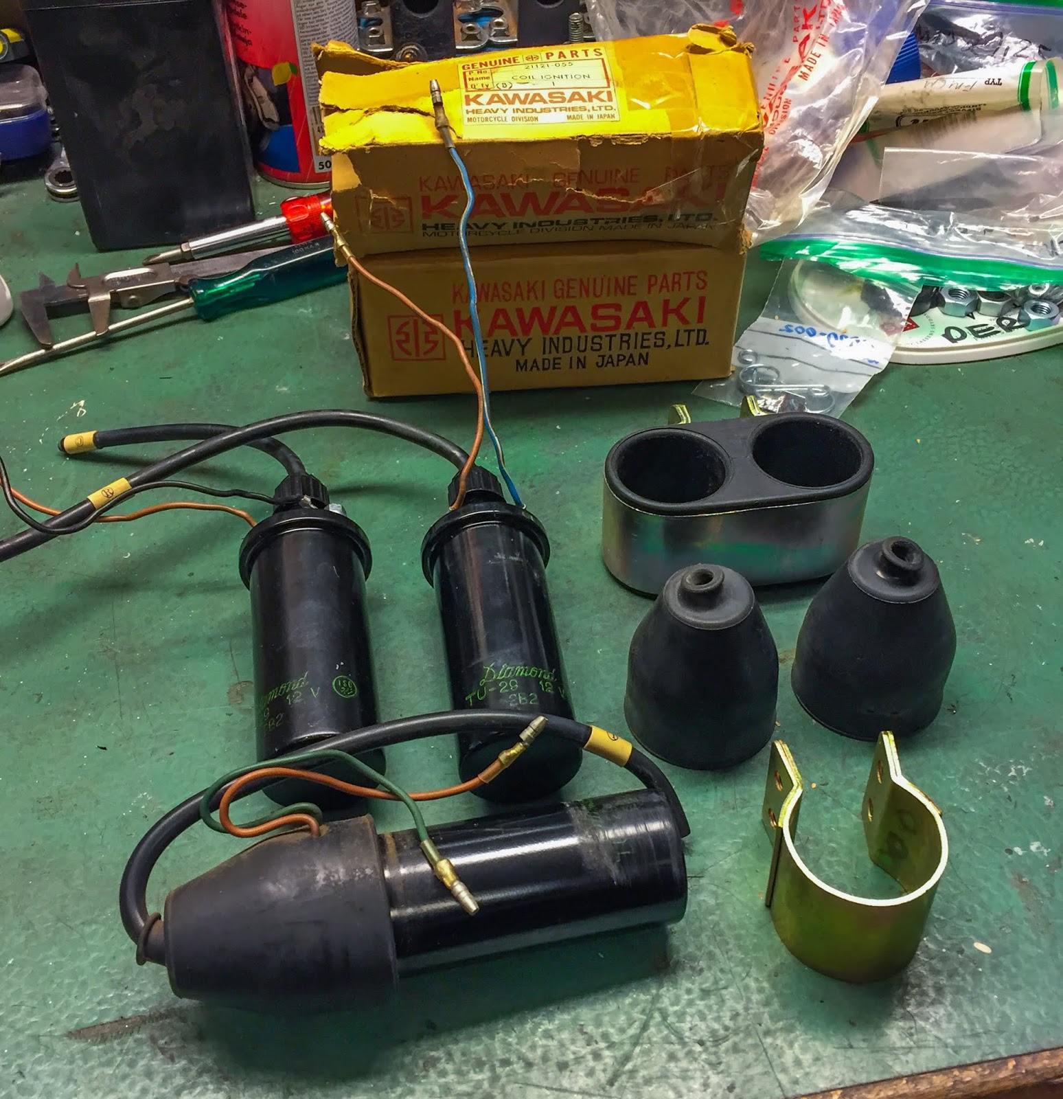
To the appropriate here’s what´s happening the bike. Three H1B coils and the clamps from the Kröber coils plus that small, sq., half that´ll work as a spacer for the 2 coils below the steering head. They’ve all been refurbished and rezinked. Sorry to say, even the proper H1R ignition coil clamps, 92037-052, are not possible to seek out… These will work tremendous, although.

Three “Diamond” coils able to be mounted to the racer. Word that the present feed strains are all brown and the others are color-coded to suit L,C and R cylinders on the H1B 1972.

Up to now so good, The components in place. The ultimate fitment will in all probability be considerably totally different so I´m not tightening the components totally simply but. No security wiring both since my expertise tells me I´m going to alter every thing a minimum of two or 3 times…
Earlier than placing these components on I additionally needed to straighten the “spear” a bit. I seen it didn´t line up completely with the bike´s heart line. Straightforward repair in my massive vise. The rod is produced from very thin-walled tubing and will simply be massaged straight. With out even ruining the paint. Thanks!

Now for the wiring from the engine to {the electrical} “central” up entrance. I´m simply making an attempt to hook issues as much as get a really feel for the size of the wiring and the place to find it when the time comes. Placement of the wiring is essential on many bikes to have the ability to get room for all cables and many others that must go near the steering head. On Honda CBX:s there´s even a “wiring tracing diagram” to comply with so as to get every thing in place. No want for that right here, although.
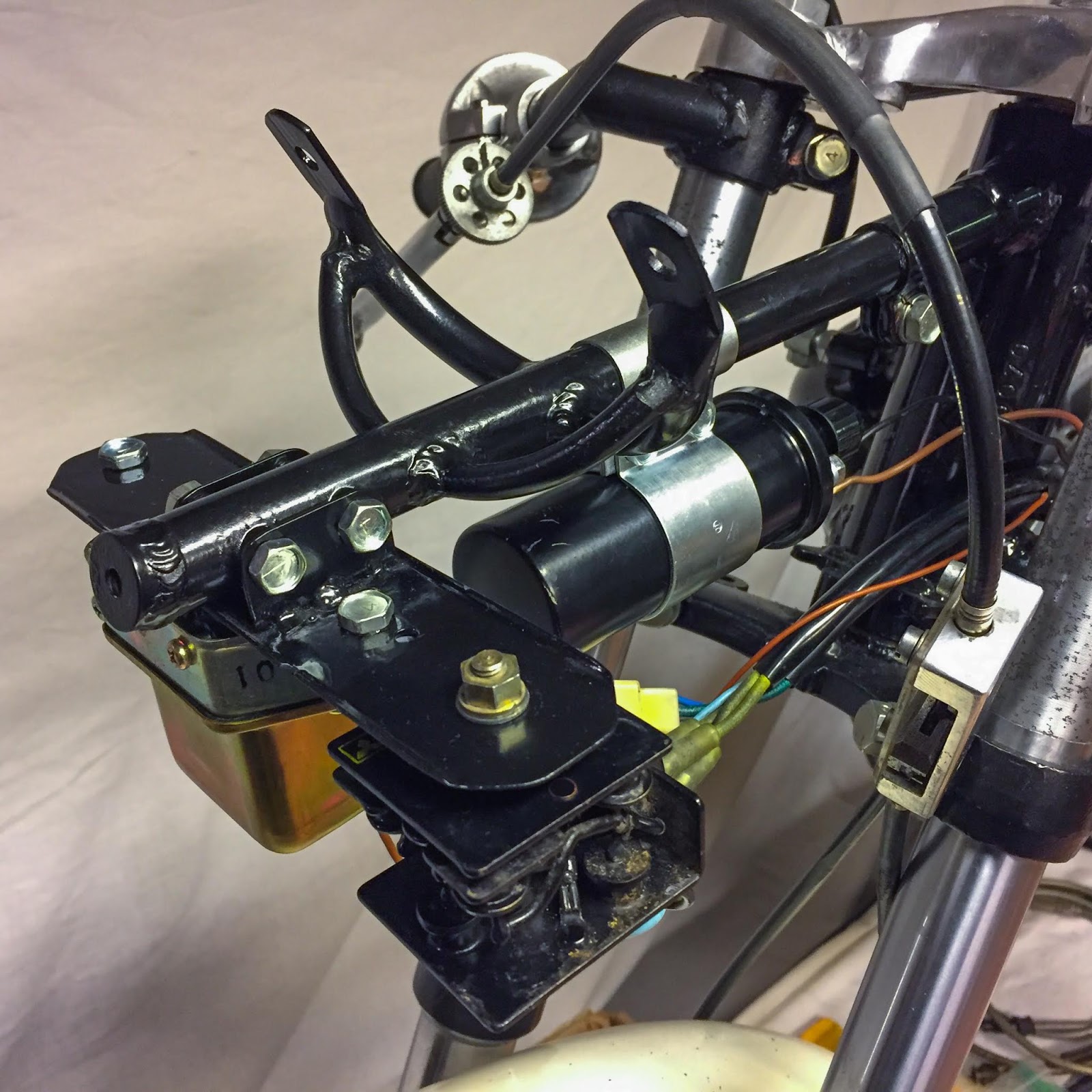
Right here I’ve managed to get the 2 entrance coils in place. I imagine these two would be the left and proper cylinder and the one up entrance would be the heart one. That appears to make most sense right here. After all I needed to transfer these additional rear than I would love, however these coils is likely to be a tad longer than the unique ones they usually ended up touching the body tubes if not slided far to the rear of their clamps.
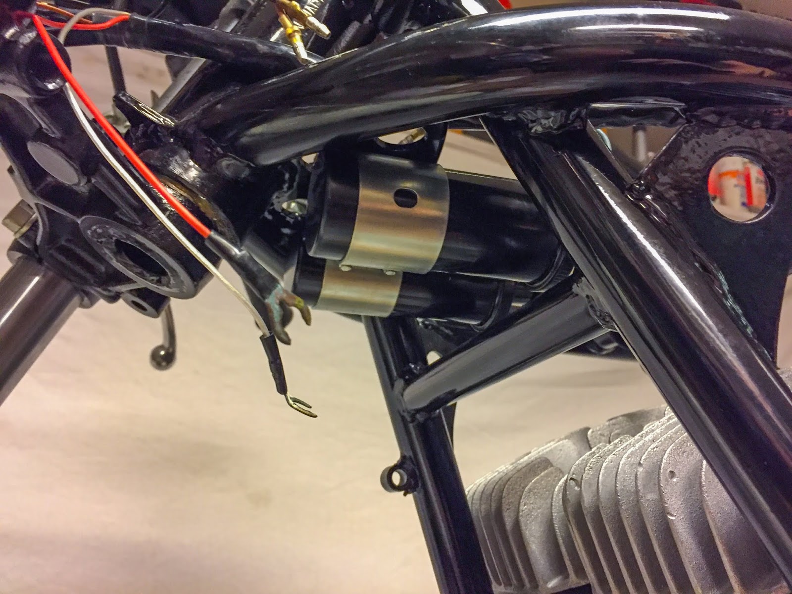
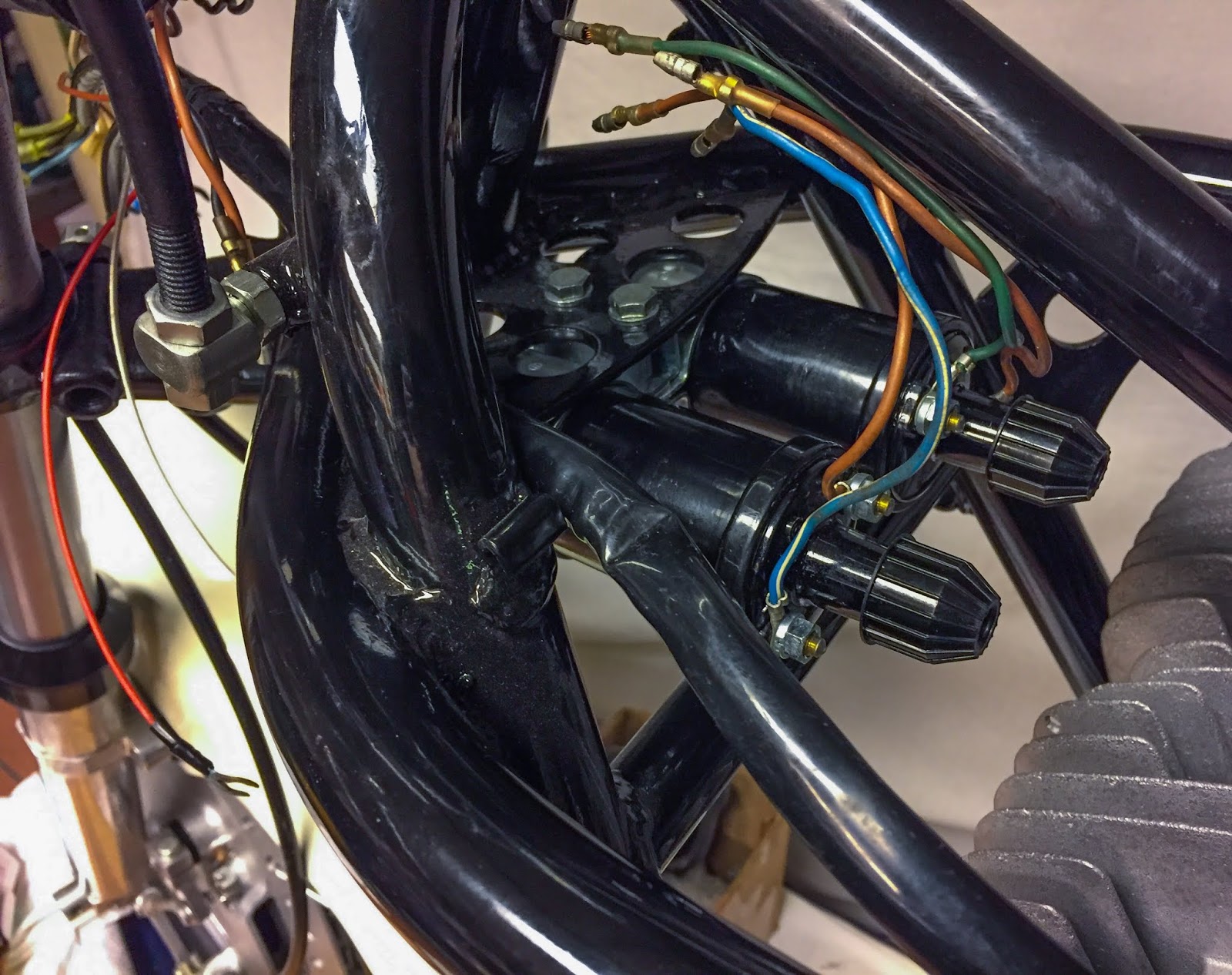
A peek from under. There they’re, snugly and tightly fitted with out touching the body. It actually doesn´t matter that a lot since they’re mounted strong to the body anyhow. And that goes for the unique coils as properly. The precept is identical, simply totally different coils and clamps. Should you look intently you possibly can see the color-coded cables popping out from the wiring. Those with open connectors are those going to the totally different coils. I would like to suit the wiring in a location the place all coils will be linked with out stretching the cables. It´s going to finish up someplace near the place it’s proper right here!

Let´s attempt to match the tank… Labored tremendous! I do imagine the wiring should go on the surface of the body tubing. We´ll see about that later when it´s time to place it on completely. For now I can get pleasure from this view of the bike with some extra electrics on!

Time to maneuver on to the drive chain. The issue with that was I needed to get the clutch cable cleaned, lubricated and mounted on the clutch lever plus engine clutch launch.
Right here we go!
The H1R clutch cable has no adjuster halfway between the engine and the deal with bar as do the road bikes. I had a plan to interchange my previous, authentic one, with a really good used road mannequin clutch cable.
Two issues: it was too lengthy and the adjuster would find yourself proper the place you possibly can see it. Not good. An excellent clear and a stress lube of the H1R cable needed to do…
Right here it’s hooked up up on the clutch lever. I most frequently discover it simpler to lock it on the lever first after which on the engine.
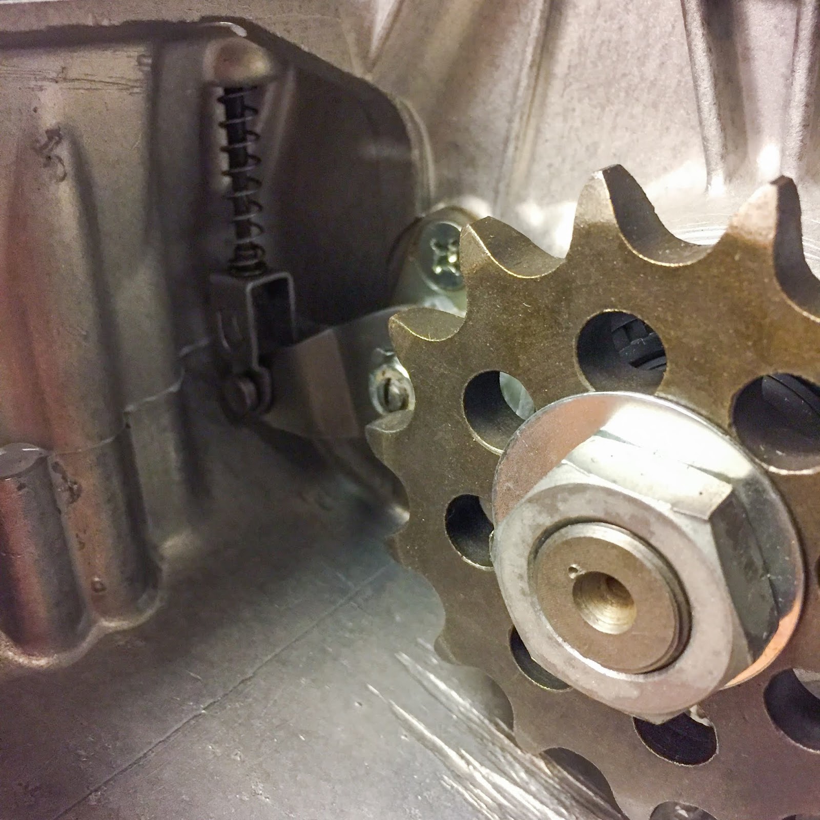
And right here´s the rationale why it is advisable to join the clutch cable earlier than placing the chain on…. When the chain is on, it’s virtually not possible to succeed in the clutch launch and adjusting it.
Right here it’s hooked up AND accurately adjusted. When the discharge lever is resting on the approx 8 o´clock place with solely minimal free play you´ve acquired it right. Think about the place the pressure you pull on the cable with will do probably the most good. Yeah, at 9 o´clock, at a 90-degree angle.
If extra play develops throughout driving you alter on the deal with bar lever till it’s important to get again down right here and readjust on the launch. Relatively ingenious really!
The video under reveals how the clutch works. very cool to have the ability to see the motion on a bike clutch in actual life! These infants are most frequently hidden behind engine covers and run in oil and may by no means be seen.. Good!
OK, the clutch is working. Drive chain up subsequent. I purchased a easy, non-O-ring, 530 DID chain. After all it was means too lengthy… It needed to be lower to suit the bike. One would suppose, in any case these years, I might have gotten myself a series riveting/chain chopping device. No, I didn’t. I do it the quaint means. First I must measure what number of hyperlinks to take away. I discover is best to measure on the rear sprocket. Be sure you have the wheel at its front-most place within the swing arm. Stretch the chain as exhausting as you possibly can by hand and place the proper hyperlink subsequent to the tip hyperlink. make sure to get two “inside” hyperlinks subsequent to one another. If not, you´ll find yourself needing a “half hyperlink” to get the chain collectively. That’s pointless in 95 % of the circumstances.
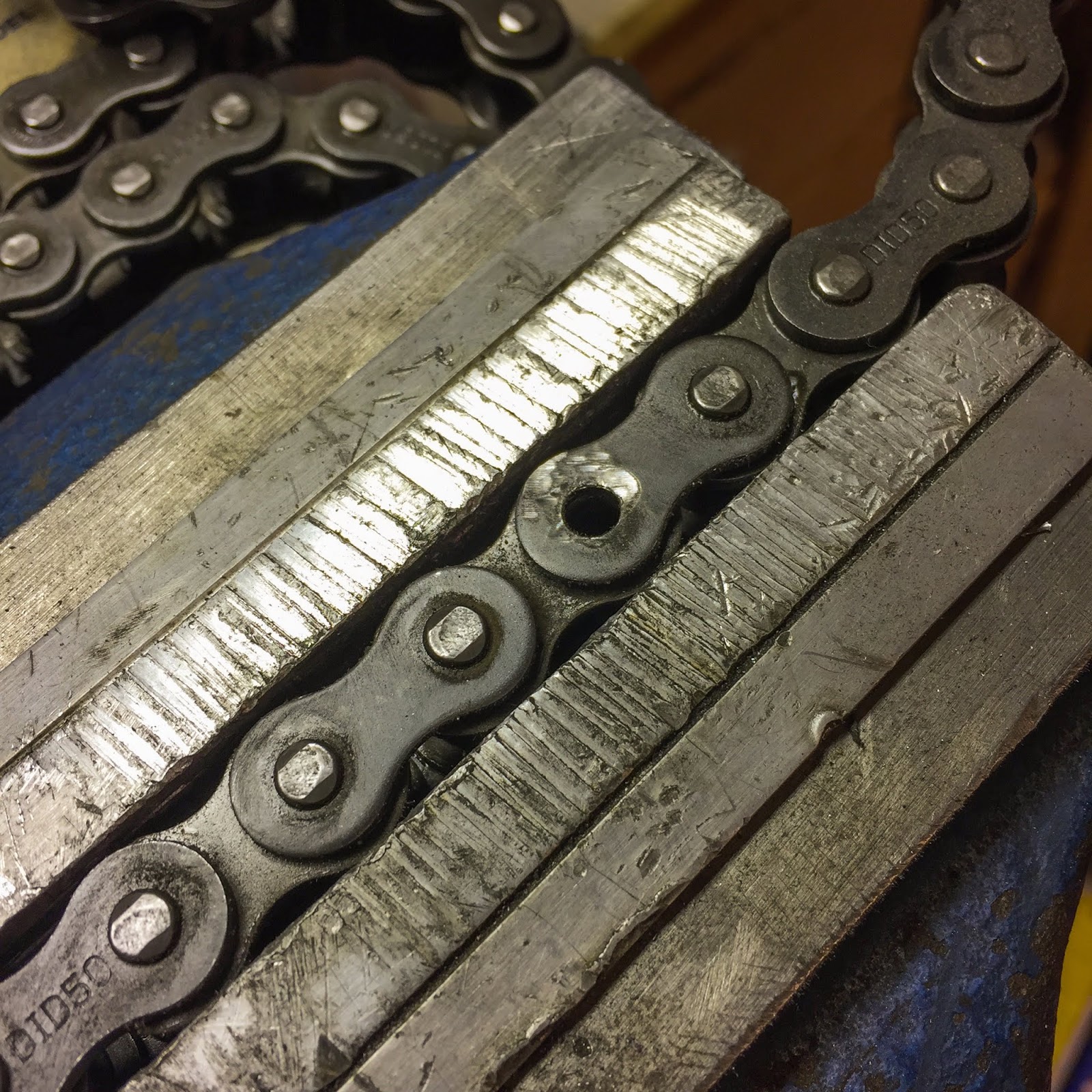
After getting determined the place to chop the chain, mark that very rivet rigorously after which grind it off with a grinder or Dremel toool. Then use a small mandrel and hammer to get the rivet out. And there you go! Chain lower to measurement…
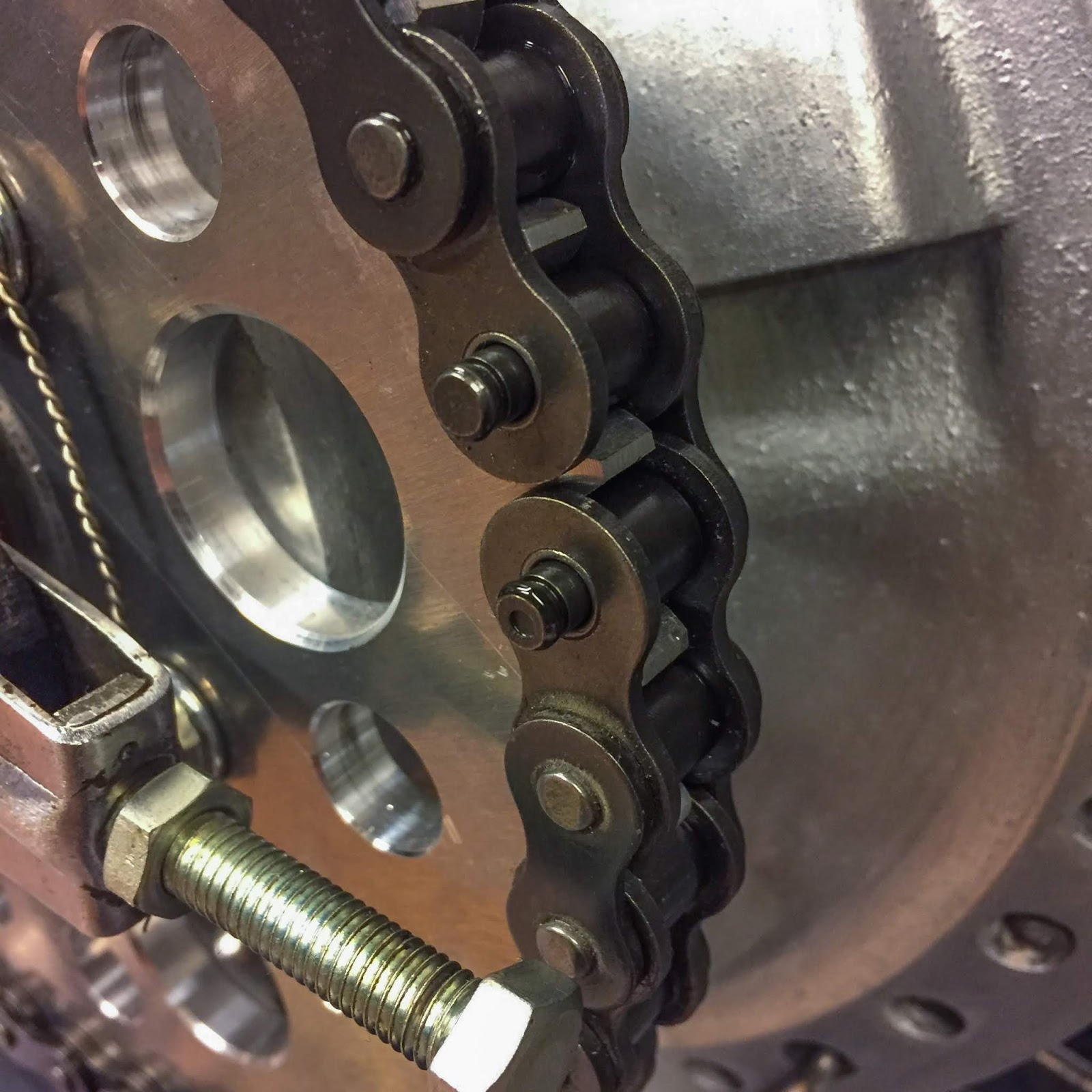
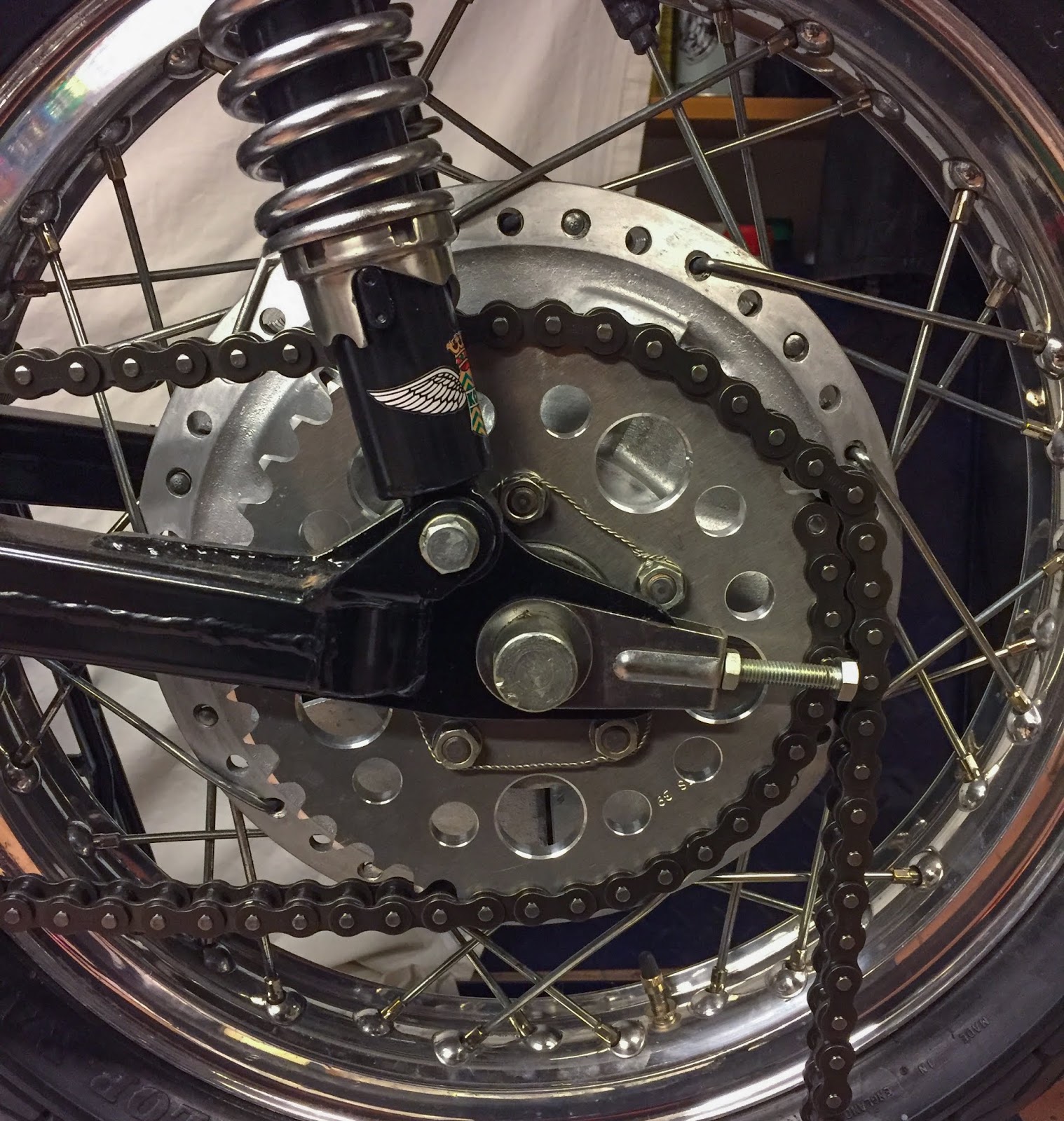
To the appropriate you possibly can see why you will need to lower the proper hyperlink. The chain lock goes in from behind and now the chain will keep in place all by itself.

When the hyperlink cowl is in place you set the chain lock clip in place with the opening dealing with away from the chain´s drive path. This clip can later be secured in a few methods. I´ll most actually use security wiring. Many do use silicone to maintain it from rattling unfastened, however I imagine wiring was extra generally used throughout the day.

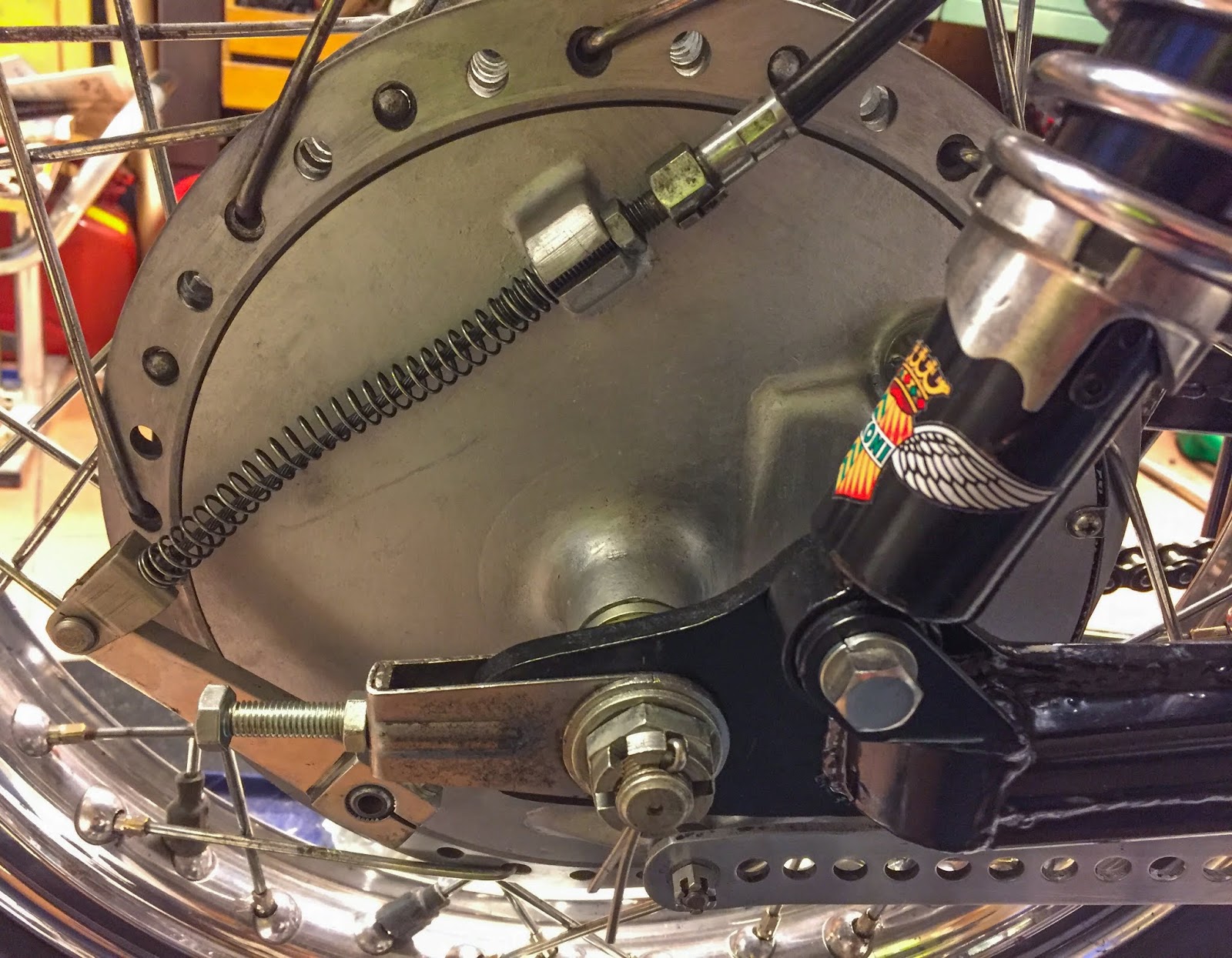
Subsequent up was getting the rear wheel completely hooked up to the swing arm. I needed to handle the attachment of the rear brake cable on the wheel and rear brake pedal place adjustment screw.
To do that I needed to get the bike off the stand and down on the ground. The rear brake pedal attaches to the appropriate, rear foot relaxation and that needed to come off to alter the place of the screw.
To the appropriate right here, job is finished!
I’ve the screw head under the bracket and the lock nut above. This fashion it labored out tremendous with the pedal at place adjustable up and down a bit.

On the rear wheel every thing is finished now. Rear brake cable hooked up and adjusted, rear wheel adjusted within the swing arm for proper chain rigidity and line-up with the engine sprocket. I discovered an ideal measurement cut up pin for the rear axle nut, please be aware it isn´t totally put in but, I’ll most actually take away the wheel a minimum of two or 3 times extra earlier than that is achieved…

I additionally needed to repair the bracket for the tachometer. Keep in mind I had it refurbished some time in the past with new rubber vulcanized to my authentic metal components? It simply needed to be painted to go on the bike. Half an hour of masking and a rattle can spray of semi gloss wheel paint acquired that sorted. I’ve no issues utilizing the marginally inferior spray colours from cans for the reason that coats of paint on these bikes actually are very skinny and largely with none primer in any respect. Nicely, right here it’s, drying over evening.

I’ve many small issues I would like to repair everywhere. The bracket for the “chain cowl” was one among them. I measured the tube the place it goes and purchased a number of totally different ones from eBay. the unique half?
36024-003.. Yeah, been on the lookout for ages…. No Pleasure! Right here´s the one which was closest in diameter. 92037-1115. Muffler Clamp from KLT 250. I acquired two and modified one among them to suit my functions.
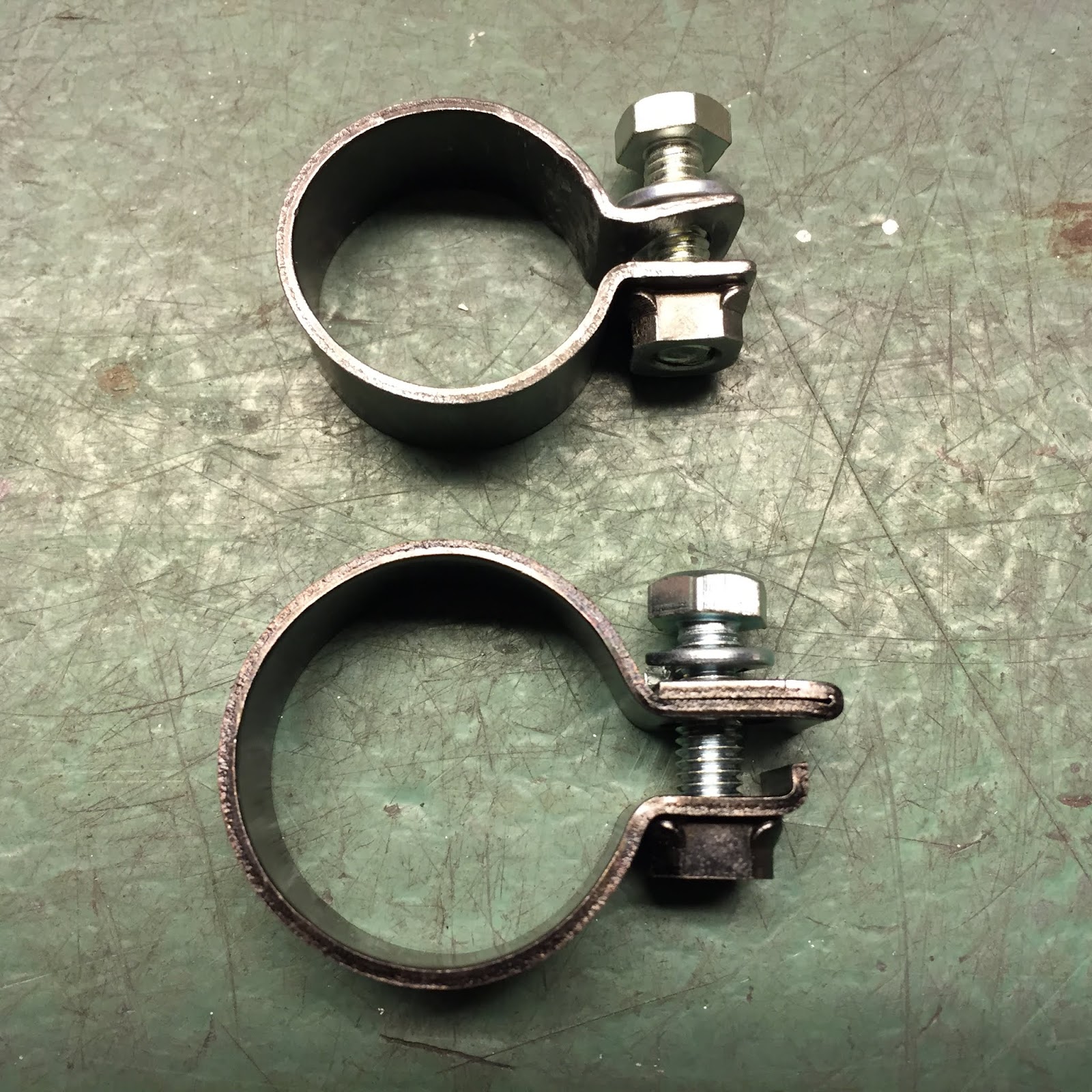
I needed to make it a bit of smaller and alter the path of the bolt brackets a bit. The welded-on nut may stay, it appears the half! It was roughly excellent to only lower off the half with the bolt gap after which therapeutic massage it again to the round form however with the proper diameter. Now it is usually prepared for paint.

And right here´s the chain guard with the clamp able to go on the bike, as soon as the clamp has been painted gloss black. I will even must drill the outlet within the entrance finish of the guard. That finish additionally needs to be angled a bit… ideally earlier than drilling. These are all small, straightforward duties that wants no greater regarded as accomplished. Just a few good fettling within the storage.
That sums all of it up for in the present day! Work is ongoing now and progress is being made slowly however safely. It helps having 8 days off work right here over Christmas and New Yr… By the way in which, If I didn´t say it earlier than:
HAPPY HOLIDAYS AND A HAPPY NEW YEAR TO YOU ALL!!
In 2019 this 1970 Kawasaki H1R will hopefully be achieved and up and working. Maintain you fingers crossed!
/Per
[ad_2]